|
CFH12K Field Bright Stars Mapping
|

|
Telescope Field Mapping (TFM) Documentation Page
Table of contents:
Use TFM Now
WHAT ANY CFH12K USER SHOULD KNOW
 The ``Telescope Field Mapping'' (TFM) tool maps the bright
stars in and around the field of view of CFHT's wide-field
CCD imager CFH12K. Bright stars
are the prime source of image contamination in CCD wide-field imaging:
large halos, scattered lights and blooming cause far more pixels to be
lost for science than bad cosmetics in particular. Statistics show that
there is a least one 8th magnitude star per square degree in the sky.
It is obvious that any CFH12K field of view will include several fairly
bright stars.
The ``Telescope Field Mapping'' (TFM) tool maps the bright
stars in and around the field of view of CFHT's wide-field
CCD imager CFH12K. Bright stars
are the prime source of image contamination in CCD wide-field imaging:
large halos, scattered lights and blooming cause far more pixels to be
lost for science than bad cosmetics in particular. Statistics show that
there is a least one 8th magnitude star per square degree in the sky.
It is obvious that any CFH12K field of view will include several fairly
bright stars.
Any CFH12K observer should check
his pointings using this tool to ensure that no major bright stars
related problems (see items 1, 2 & 3 below) will badly obliterate
the data. Of course, there are times when the object of interest
can not be moved significantly enough on the CFH12K field of view
to avoid contamination, but there are ways to at least minimize the
impact of these bright stars.
Note that the CFHT prime focus
bonnette can not be rotated, hence dodging bright stars can only be
accomplished through translations along the alpha and delta axis.
TFM respects the size and gaps
between the CCDs as well as the off-centered position of the telescope pointing
(the point of the sky corresponding to the telescope pointing coordinates
lies on the top corner of CCD02, not exactly at the center of the mosaic.
See this
page for further information.)
However be aware that the gaps between the CCDs are not perfectly uniform, nor
are the CCDs perfectly aligned in respect to each other (typical alignment angle is 0.3 degree),
and can play a role at the scale of 10 arcseconds (see the "Mosaic Geometry" section
on this
page for further information.). So don't count on TFM to
position an object precisely in a gap for example. Worse, the rotation of the
camera on the sky is defined by the alignment of the telescope prime focus top-end
at installation at the beginning of the observing run. Due to innacuracies in the
process, the alignment of the instrument changes by up to 0.5 degree from an
observing run to another. TFM maps the sky on the CFH12K field for a rotation
angle of 0 degree, hence a small rotation induced by the mounting process will
shift all the positions by as much as 20 arcseconds in the outer parts of the field.
Also, the telescope pointing accuracy is roughly 10 arcseconds unless a SAO star
is used to reset the pointing just before. A SAO star pre-pointing allows a
pointing accuracy on a nearby field of 1 arcsecond but the process of calibrating
on the SAO stars eats up 2 to 3 minutes. So, all in all, TFM can not (so
could not
any other tool) be used to prepare CFH12K pointings more accurate than 10 arcseconds.
A sinus projection is used to map the Guide Star Catalog objects on a two
dimensional plane. Moreover, the CFHT prime focus wide-field corrector
optical distortion is included in the star positions mapping. A common effect for
such optics, this radial distortion increases the actual distance of objects to
the center of the field (see Cuillandre et al. PASP, 1996, 108, 1120).
THE MAIN REGIMES OF BRIGHT STARS CONTAMINATION
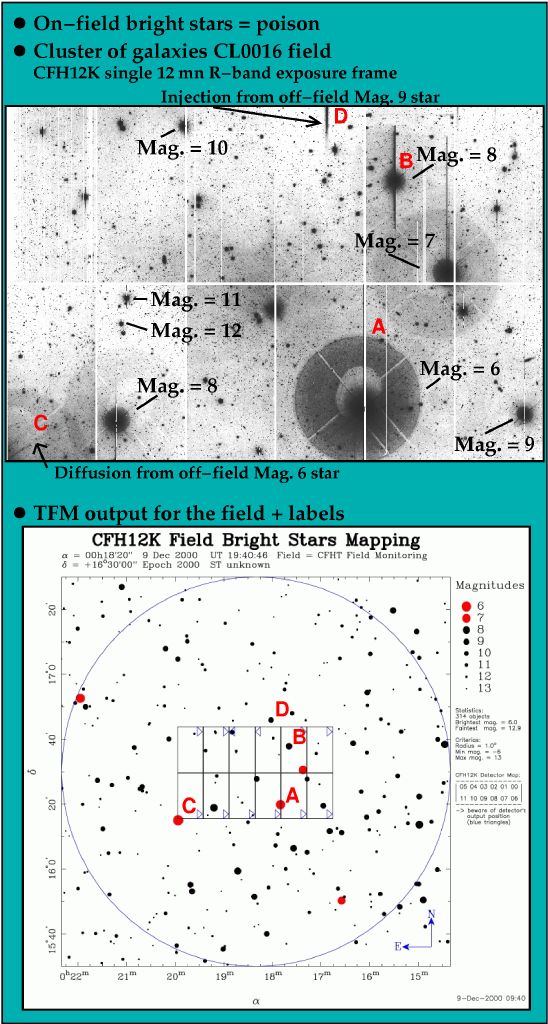
1: On-field stars
This slide illustrates
how bright stars falling within or near the CFH12K field of view can
badly degrade the quality of the data. Here are described the four
typical cases of contamination caused by bright stars: reflection
halos, blooming and scattered light from the edge of the focal plane.
The letters pointing the various phenomena on the slide are described:
- A: The transmission of the optics (dewar window, filters, wide-field
corrector lenses) are less than 100% (usually 96% with coatings).
The surface of the CCD itself is reflective (specially in the blue)
and light bounces back from the CCD to the dewar window, then back
to the CCD. This is what can be seen as the "A" effect: a very
large halo (7 arcminutes diameter). This halo does not unfortunately
produce a uniform illumination and it can be difficult to salvage
objects lying in that area. This effect is critical for stars
of magnitude less or equal to 6 (V-band). Note that the flux
in this halo is no more than 1% of the overall flux from the star.
For fainter objects, this halo is totally dominated by the sky
background photon noise and does not affect the signal.
Check out the "tips" section below about the limits one should
set on the on-field stars.
- B: The pixel full well capacity is about 100,000 electrons. Beyond
that, the
electrons start overflowing on the surrounding pixels along the
columns. A bright star can easily contaminate entire columns of
a CCD, resulting in dead scientific area far away from the star
itself. This effect kills less data than the halos.
- C: When a star lies near outside the edge of the CCD focal plane
there is still some reflections effects happening with the
light baffle inside the CCD dewar. The contamination is much
lower (factor of 5) than in the case A though.
- D: When a star is a bit more further out in the field, its
light hits the edge of the filter (which have baffles that
reduces the effect but don't eliminate it) and results in
an injection light beam on the CCD. This can spray light
onto the CCD focal plane up to 7 arcminutes from the edge.
This is the less damaging effect.
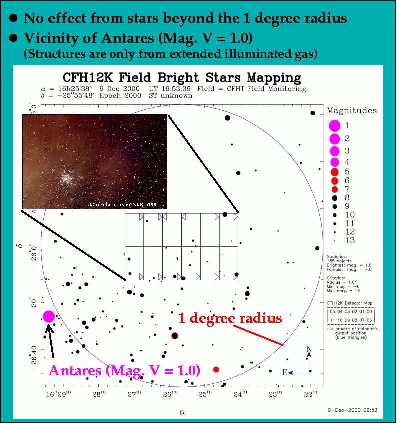
2: Within 1 degree radius stars
Baffling and surfaces blackening have been greatly improved at CFHT's
prime focus prior CFH12K first light in 1999. While UH8K used to suffer
a lot from stars within the field of view of the wide-field corrector
in particular (0.5 degree radius), the effect on the CFH12K has been
strongly reduced (factor of 10). The tests shown on this
slide illustrate the effect caused by the star Sirius, the brightest star
in the sky
(the star was positioned at various locations around the field of view
of CFH12K as illustrated by the small images distribution).
For all the other stars in the sky, the effect will be lower of course
(scaled by their relative brightness), often dominated by the
sky photon noise, but still present.
3: Beyond 1 degree radius stars
Stars beyond that limit are not a concern anymore. This is illustrated
by this slide.
TIPS TO MINIMIZE CONTAMINATION FROM BRIGHT STARS
1:
Look at the TFM output for the wished pointing. If there
is a bright star of magnitude less than 4 within the 1 degree
radius, try to compromise the pointing to put the star as close
as possible from, or outside, the 1 degree radius area. Iterate
using the "Display GIF Image" option.
2:
Look at the TFM output for the wished pointing. If there
is a bright star of magnitude less than 7 inside the CFH12K field
of view (the mosaic), try to compromise the pointing to put the star outside
the focal plane. However, you have to expect the following item 3.
Iterate using the "Display GIF Image" option.
3:
Look at the TFM output for the wished pointing. If there
is a bright star of magnitude less than 6 outside and very near
(less than 1 arcminute)
the CFH12K field of view, try to compromise the pointing to put
the star further away (like 2 arcminutes). However, you have to
expect the following item 4.
Iterate using the "Display GIF Image" option.
4:
Look at the TFM output for the wished pointing. If there
is a bright star of magnitude less than 8 outside and near (more than
1 arcminute)
the CFH12K field of view, try to compromise the pointing to put
the star further away (3 arcminutes).
Iterate using the "Display GIF Image" option.
HOW TO EFFICIENTLY USE TFM
To properly select the correct pointing on your field, iterate a few
times until the brightest stars don't represent a serious danger anymore.
For angular scaling reference, the individual detector size is 7'x14'.
The center of the field is given in the text area on top of the window
while the axis are labelled in arcminutes with the reference (0,0) set
at the center of the mosaic.
A radius of 1.0 degree is used for checking for bright stars contamination.
As shown above, even extremely bright stars are not a problem
beyond the 1 degree radius.
TFM can also be used to produce CFH12K finding charts
(use a of radius of 0.4 degree). Access this fonction with this
link.
TFM also runs in ``monitoring'' real-time mode during
observations giving the map of the field currently pointed by
the telescope (1.0 degree radius, no input from the user).
Known problem: TFM fails if a pole (+90.0 or -90.0) is included in the field (projection problem).
EXAMPLE OF TFM OUTPUT
Comments on the CFH12K pages to Jean-Charles Cuillandre:
jcc@cfht.hawaii.edu
``Telescope Field Mapping'' was developed by
Frédéric Magnard (CFHT) and Jean-Charles Cuillandre (CFHT).
CFH12K
is the CFHT CCD wide-field imaging mosaic.
|