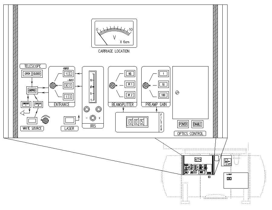


 The auxiliary control environment, shown in Figures 3.9 and 3.10, can be
divided
into four separate areas: (1) the master power switch, (2) the laser
power
switch, (3) the aperture wheel controller, and (4) the auxiliary control
panel. Each of these are discussed below.
- The master power breaker:
This switch controls all power to the FTS, and
must be turned on prior to observation. This is the first switch to be
turned
on at the beginning of each night, and the last to be turned off at the
end
of each night.
- The laser power switch:
This switch activates the reference laser. In
order to monitor path difference effectively, the resonance lines in the
laser
signal must be extremely stable. This is done by housing the laser in a
special
thermal environment, and it takes about half an hour for the temperature
of the laser to stabilize sufficiently before the servo system can be
locked.
The stability of the laser can be monitored using the R1/R2 oscilloscope
(Section 3.1.4).
- Aperture Wheel Controller: The aperture cold stop selection is carried
out with the aperture wheel controller. The aperture wheel can be
rotated in only one direction (
 ) and any change in the aperture
must be accompanied by a carefully choreographed change in the FTS
filters. As an example, assume you have been observing with filter #3
and aperture #4 but want to change to aperture #2. First, move the
filter wheel to position #0 (open) and wait for the green ready light to
be illuminated on the aperture wheel controller. Now move to aperture #1
by turning the aperture control knob to the appropriate position. Again
wait for the green ready light to come on. When it does, reinsert filter
#3. You must then step through the procedure once more: filter #0,
aperture #2, filter #3, waiting for the green ready light before
proceeding with each step. This procedure is also outlined on the
aperture wheel control itself for handy reference at the telescope.


- The Auxiliary Control Panel:
The auxiliary control panel is almost an
exact duplicate of the `instrument set up' portion of the master control
panel. These controls should only be used after the Section 3.1.1 has been disabled. The one difference between the two
control panels is that the beam splitters can be changed only from
the auxiliary control panel with the switch marked `beam splitter'.
The beam splitters should only be changed in one
direction, which is in the sense VIS
 IR1
IR1  IR2
IR2  VIS... Moreover, the beam splitter carriage should only
be advanced one setting at a time, and the assembly should be allowed
to come completely to rest before proceeding to the next setting. This
usually
takes
  seconds; there will be a moderately loud whirring noise (
 seconds) caused by the motion of the beam splitter assembly, followed by
a fainter whirring noise (
 seconds) while the brake engages. As an example, if you are currently using the IR2
beamsplitter and want to change to IR1 you must first change to VIS,
wait for the two whirring noises to end, and then change to IR1.
FAILURE TO
FOLLOW THIS PROCEDURE WILL CAUSE THE LIGHT PATH TO BECOME
MISALIGNED.


The auxiliary control environment, shown in Figures 3.9 and 3.10, can be
divided
into four separate areas: (1) the master power switch, (2) the laser
power
switch, (3) the aperture wheel controller, and (4) the auxiliary control
panel. Each of these are discussed below.


