CFHT – CAFE
CAssegrain
Fibre Environment
Documentation
- Maintenance Manual
![]()
 People implied on the project
General Management and Optics :
Jacques BAUDRAND Observatoire de Paris-Meudon
Tel : (33) 1 45 07 75 17 E.mail : jacques.baudrand@obspm.fr
Electronics :
Rene VITRY Observatoire de
Paris-Meudon
Tel : (33) 1 45 07 75 41 E.mail : : vitry@obspm.fr
Mechanics :
Michel
LESSERTER CNRS Meudon Bellevue
Table
of Contents
1 Overview................................................................................................ 5
1.1 Purpose of CAFE....................................................................................................................................... 5
1.2 Functional and Performance
Specifications (high level)................................................................. 5
1.3 Main Features............................................................................................................................................ 7
2 Instrument Description.................................................................... 7
2.1 Sky Fibre..................................................................................................................................................... 7
2.1.1 Fibre optical
characteristics............................................................................................................. 7
2.1.2 Fibre structure.................................................................................................................................... 8
2.1.3 Fibre
terminations and connectors................................................................................................ 10
2.2 CAFE Head............................................................................................................................................... 11
2.2.1 Central Optical
Sub-Assembly (COSA)........................................................................................ 14
2.2.1.1 Viewing Optics........................................................................................................................... 17
2.2.1.2 Calibration
Optics...................................................................................................................... 17
2.2.2 Calibration
facility.......................................................................................................................... 18
2.2.3 Mirror Wheel................................................................................................................................... 19
2.3 Gecko Interface....................................................................................................................................... 20
2.3.1 Mechanical
design........................................................................................................................... 20
2.3.2 Optical design.................................................................................................................................. 21
3 Procedure for the
Opto-mechanical Settings of CAFE......... 23
3.1 For the CAFE Head................................................................................................................................ 23
3.2 For the Gecko Interface........................................................................................................................ 24
4 Telescope Field
acquisition and Tracking................................. 24
5 Instrument Efficiency on
the Sky................................................ 25
5.1 Sky Fibre Link transparency................................................................................................................ 25
5.2 CAFE versus Coude Train Overall
Efficiency.................................................................................. 27
6 Component Maintenance................................................................. 28
6.1 Spares........................................................................................................................................................ 28
6.2 Parts Replacement................................................................................................................................. 29
6.2.1 Calibration sources......................................................................................................................... 29
6.2.2 Opto-detector
fork mount.............................................................................................................. 29
6.2.3 Moto-reducer
and driving Belt....................................................................................................... 29
6.2.4 Sky Fibre.......................................................................................................................................... 29
7 Electronics........................................................................................ 30
7.1 Description.............................................................................................................................................. 30
7.2 Operation................................................................................................................................................. 33
7.2.1 General............................................................................................................................................. 33
7.2.2 About the
Manual Command.......................................................................................................... 33
7.2.3 About the
Loading of the Control Program.................................................................................. 35
7.2.4 About Automatic
Safety.................................................................................................................. 35
7.2.4.1 LLLTV Interlock......................................................................................................................... 35
7.2.4.2 E.M Interlock.............................................................................................................................. 35
8 Control Program and Logic
Syntax........................................... 36
8.1 Control Program Upper Level Flow Chart...................................................................................... 36
8.2 Program Logic Syntax........................................................................................................................... 39
9 Commercial Part List....................................................................... 42
10 Annexes................................................................................................ 44
10.1 Optical data......................................................................................................................................... 44
10.1.1 Viewing Optics................................................................................................................................ 44
10.1.2 Calibration
Optics........................................................................................................................... 45
10.2 Electronics.......................................................................................................................................... 46
10.2.1 Cards Circuit
Description............................................................................................................... 46
10.2.1.1 ThAr Card............................................................................................................................... 46
10.2.1.2 Logical Card........................................................................................................................... 48
10.2.1.3 Power Card............................................................................................................................. 53
10.2.1.4 LLLTV
Interlock.................................................................................................................... 55
10.2.1.5 Manual
Command Card......................................................................................................... 56
10.2.2 Tests
points and Back Plane Connectors....................................................................................... 58
10.3 CAFE Control
Program................................................................................................................... 60
10.3.1 Listing of the
assembler program loaded into the micro-controller 68 HC 811...................... 60
10.3.1.1 Part 1 Main Program............................................................................................................ 60
10.3.1.2 Part 2 Serial Interpretation.................................................................................................. 63
10.3.1.3 Part 3
Interruptions............................................................................................................... 71
Table
of Illustrations
Figure 1 Summary of
CAFE main Functions and Specifications....................................... 6
Figure
2 Schematic view of the fibre
optical characteristics...................................... 8
Figure
3 CeramOptec Transmission versus classical “Wet” and “Dry” fibres........ 9
Figure
4 Schematic view of the Fibre
Radial Structure................................................... 10
Figure
5 Drawing view of the Precision
Fibre Connector............................................... 10
Figure
6 Fibre ferrule extremities with
their cemented microlens....................... 11
Figure
7 Picture of the CAFE Head fully
assembled........................................................... 12
Figure
8 CAFE Head with Cover removed
Mounted on Cass. Bonnette..................... 13
Figure
9 Drawing top view of the CAFE
Head........................................................................... 13
Figure
10 Pictures of the Central Optical
Sub-Assembly (COSA)................................... 14
Figure
11 COSA General Opto-mechanical
Overview............................................................ 15
Figure
12 COSA general optical arrangement......................................................................... 16
Figure
13 Calibration Fibre Feed
arrangement....................................................................... 18
Figure
14 Drawing view of the Mirror Wheel.......................................................................... 19
Figure
15 Drawing view of the Gecko
Interface..................................................................... 20
Figure
16 Gecko Interface under test for
control of output beam N.A.................. 21
Figure
17 Gecko Interface Optical
Characteristic............................................................... 21
Figure
18 Views of the Bowen Wallraven
Image slicer...................................................... 22
Figure
19 Photometric Attenuation Budget.............................................................................. 26
Figure
20 Comparison between CAFE and
Coude Train Efficiencies............................. 27
Figure
21 Spare List................................................................................................................................... 28
Figure
22 Electronics Main Parts
Presentation...................................................................... 31
Figure
23 General Organisation of the
Electronics Main parts.................................. 31
Figure
24 General Architecture Synoptic of
the Electronics....................................... 32
Figure
25 Manual Command Front Panel.................................................................................... 34
Figure
26 Upper Level Flow Charts of the
Control Program........................................ 39
Figure
27 Table of the Logic Commands,
Queries and Errors......................................... 40
Figure
28 Mirror Wheel
Opto-Electrical-Logic Relations............................................... 41
Figure
29 Commercial Parts List and
Suppliers/Manufacturers co-ordinates... 43
Figure
30 Viewing Optics Listing and Spot
Diagrams............................................................. 44
Figure
31 Calibration Optics Listing and Density diagram............................................... 45
Figure
32 Block Diagram of the ThAr Card................................................................................ 46
Figure
33 Diagram showing the ThAr Card in
its Electronics Environment.......... 47
Figure
34 Block Diagrams of the Logical
Card Architecture....................................... 49
Figure
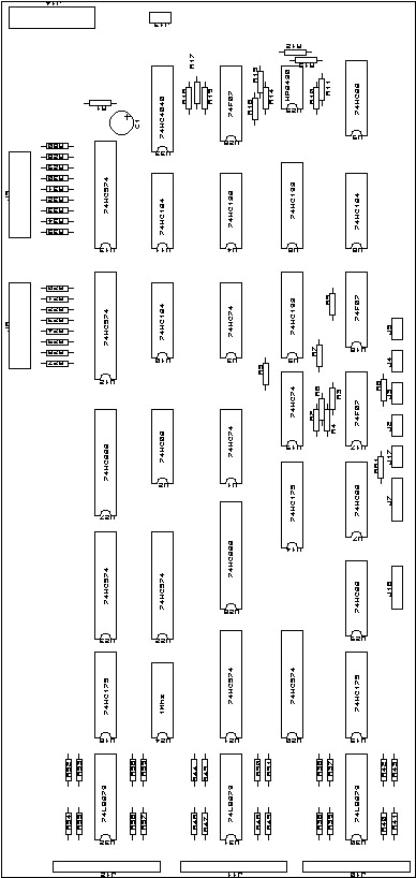
35 Component Layout of the Logical
Card................................................................ 50
Figure
36 Circuit Diagrams of the Logical
Card Architecture..................................... 52
Figure
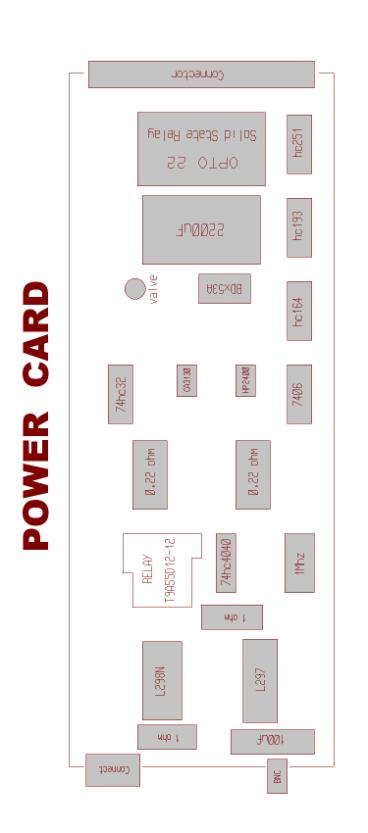
37 Component Layout of the Power
Card................................................................... 53
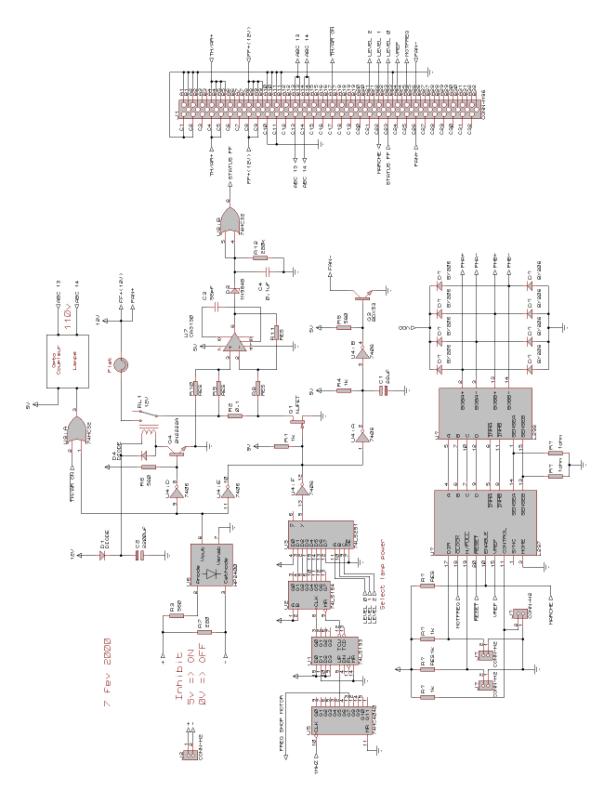
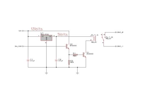
Figure
38 Circuit Diagrams of the Power
Card Architecture........................................ 54
Figure
39 Detail of the LLLTV Interlock....................................................................................... 55
Figure
40 Component layout of the Manual
Command Card......................................... 56
Figure
41 Circuit Diagram of the Manual
Command Card Architecture................. 57
Figure
42 Test Point-Cabling Connections
and Back Plane Connectors................. 59
1 Overview
This manual provides information on the functions, assembly, alignment procedures, supply and main characteristics-performances for the new telescope facility, the CAssegrain Fibre Environment (CAFE).
CAFE was designed and constructed during the period of May 98 to September 99 through the combined effort of the Observatoire de Paris-Meudon, the CNRS de Meudon, France and the Canada-France-Hawaii Telescope Corp, USA.
1.1 Purpose of CAFE
CAFE is a fibre feed for the Gecko spectrograph meant to replace the current Coude mirror train in the visible – red part of the spectrum (400 – 1000 nm). The fibre input end is mounted at the telescope F/8 Cassegrain focus and the fibre cord is routed to the Gecko spectrograph entrance through the west declination axis and down the west beam of the telescope. This system also provides full calibration capacity for the spectrograph and a viewing system for acquisition-guiding of the star image onto the fibre core entrance. At the other extremity the fibre end is coupled to a Bowen-Wallraven image slicer feeding the spectrograph with the required input optical characteristics.
1.2 Functional and Performance Specifications (high level)
CAFE has been designed and built to meet the following high level specifications:
• The CAFE Head shall be permanently mounted in the Cass. Bonnette side port on the south side of telescope. Its structure must not project inside or below the casting of the Cass. Bonnette.
• A viewing system must be implemented in the CAFE Head to see and guide the star image onto the fibre entrance with a 25 arcsec field of view and a sensibility allowing to work with stars up to magnitude 13.5. For this purpose it is imposed to use a tilted SiO2 plate to draw out from the telescope beam the necessary signal*. It is also demanded to use and incorporate in the system the TDC-200 Low Light Level TV camera provided by CFHT.
• The CAFE Head must contain a Th/Ar emission line comparison source and a flat field lamp, both easily accessible for replacement.
• A motorised mechanism will be implemented to allow for the selection between telescope and calibration injection into the fibre.
• Conversion optics shall be designed and provided to make the F/8 telescope beam with an unvignetted field of view of at least 1.5 arcsec matches the fibre entrance diameter
• At the fibre output end conversion optics and image slicer shall be designed and provided to give the spectrograph the required F/20 beam aperture and a 200 µm wide entrance slit.
• The fibre connectors at both ends must permit easy manual disconnection of the fibre while securing the precise positioning and orientation of the fibre extremities.
• The minimum length required for the fibre cord is measured to be 27 m.
• The optical throughput of CAFE should be optimised for the wavelength range 400 – 1000 nm.
• Spares should be provided for all fragile or expected short life parts
• The CAFE unit functions will be controlled by signals sent by the CFHT computer. An electronics control box, to be located in the Cassegrain environment, will interpret these signals and send/receive the ON/OFF and status signals to CAFE (lamps and motorised system for the telescope calibration selection).
The Figure 1 summarises these high level specifications and shows schematically the main functions and features that are to be given to the CAFE instrument.

Figure 1 Summary of CAFE main Functions and Specifications
* The tilted SiO2 plate was favoured over the scheme consisting to conjugate the fibre entrance with the central hole of a tilted mirror. Indeed this latter solution was not considered reliable for the auto-guiding as it was analysed that the sharp jumps of illumination produced by the random movements of the star image to and fro across the hole aperture could very possibly mislead the guiding system.
1.3 Main Features
The instrument is constituted of three distinct parts:
• The 27 m long fibre cord, the Sky Fibre, which optically links the telescope Cassegrain focus to the Gecko spectrograph entrance in the spectrograph Slit room. The fibre extremities are equipped with single micro optics for reshaping the optical beam at both input and output ends.
• The CAFE Head which is a small optical bench structure designed to be mounted to the South port of the Cassegrain Bonnette. It contains the precision connector for the fibre link input, a camera viewing system for targeting and tracking the telescope image onto the fibre entrance, a complete calibration unit with flat field lamp and wavelength comparison source and the motorised mechanism to select between telescope and calibration injection. The whole system is designed with a two orthogonal axis mounting which allows for the fine optical alignment with the telescope beam.
The electronics to control the functions in the CAFE Head is located in a 19” rack mounted on the Cassegrain environment.
• The Gecko Interface which supports a precision connector for the fibre output termination and the image slicer for reshaping the fibre image to the specified requirements. Both connector and image slicer are mounted onto a steering and linear motion stage to allow the optical adjustment of the fibre image injection into the spectrograph.
These different assemblies are specifically described in the following section.
2 Instrument Description
2.1 Sky Fibre
The fibre in CAFE is of course a major element. Its main characteristics were completely driven by the optical specifications set by the telescope injection and the Gecko spectrograph entrance requirements and by the necessity to enhance throughput as much as possible. The fibre cord is 27 m long, a length optimised to ensure minimum absorption and to permit the practical link between the Cassegrain environment and the Gecko entrance while providing complete freedom for the telescope motions. It is protected into a resistant but supple PVC sheath and equipped at both extremities with fast precision connectors allowing easy and reliable maintenance.
2.1.1 Fibre optical characteristics
For this particular link it was decided to adopt a solution which brings into play single micro-optics bonded on top of the fibre core at both extremities. These optics are simple rod lenses of miniature size whose main function is to perform the required focal conversion at both input and output ends of the fibre. Working into the Fabry mode they also permute image and pupil in the optical system and through this exchange provide the instrument with enhanced characteristics:
- a more stable telescope image injection into the fibre
- a flat illumination pattern inside the spectrograph and on the grating. This characteristic has the advantage to limit the central photometric obscuration inside the Gecko to geometrical proportions and to enhance its spectral stability
The lenses are cemented onto the polished fibre tips by way of the Epo-Tek 305 glue, which presents a particular good transmission in the UV-Blue range. Their external spherical surfaces are treated with an A.R MgF2 coating to limit Fresnel losses over the largest spectral range.
The fibre link optical characteristics are schematically represented below on the Figure 2.

Figure 2 Schematic view of the fibre optical characteristics
2.1.2 Fibre structure
The selected fibre has been manufactured by CeramOptec. It is of the silica/silica type with a very low presence of hydroxyl contents . It presents a core diameter of 100 mm and a classical N.A of 0.22 (maximum acceptance beam of about f/2.1). A patented and permanent hydrogen treatment has been applied to the fibre preform in order to enhance its transmission shortward of 450 nm. The fibre being of the so-called “dry” type its internal transmission is also free of the Red absorption peaks produced classically by the OH contaminated “wet” fibres.
On the Figure
3 is presented the comparative internal transmissions
of the H treated CeramOptec fibre and of the more standard “Wet” and “Dry”
silica fibres usually met in astronomical instrumentation (measured for the
same length, core diameter and cladding /core ratio).

Figure 3 CeramOptec Transmission versus classical “Wet” and “Dry” fibres
The radial structure of the fibre is presented below on Figure 4. It is worth noting that the silica cladding is over-laid by two additional layers:
- a hard polyimide layer presenting a good concentricity with the fibre core. It is on this layer that the fibre adjustment into the mechanical terminations is made. This permits to avoid the stripping of the fibre down to the rather fragile silica layer.
- a soft epoxy/acrylate buffer serving as a shock and abrasion absorber for the fibre inside its PVC external sheath. This layer is removed at the fibre extremities in order to reach the polyimide mechanical reference.
-
a 3.8 mm outer diameter multilayer PVC
sheath ( FT2S003 structure) protects the whole fibre structure from the
external environment, chiefly against compression, traction and parasitic
light. Save at its extremities the fibre is motion free inside this protective
envelope.
Caution!
Care should be taken to prevent forcing the fibre cable around bends with radius < 3 cm. Overtaking that limit could put excessive stress locally at the core/cladding interface and cause unwanted mode leakage outside the fibre conduit.
Figure 4 Schematic view of the Fibre Radial Structure
2.1.3 Fibre terminations and connectors
The connecting on a fibre is a delicate operation because it can so easily jeopardise the link throughput performance if not handled properly and for CAFE a lot of attention and precaution have been dedicated to that task. We shall note here that the termination ferrules are made of ARCAP and we used the STYCAST 2651 MM glue with catalyst 9 for the encapsulation of the fibre extremities.
The fibre connectors are all alike on CAFE and are designed to allow rapid and easy connection/disconnection of the fibre and to ensure that the precise optical alignment at both input and output is safeguarded. A drawing view of this connector can be seen on the Figure 5 below.

Figure 5 Drawing view of the Precision Fibre Connector
Caution !!
During the fibre maintenance great care must be taken with regard to the fragile extremities and particularly to their cemented microlenses that jut out over the ferrule tip. Soft rubber caps are provided and must be fitted on top of the ferrules whenever the fibre is disconnected. In that case a dedicated fibre rack is also supplied for the storage of the fibre extremities.
The next picture on Figure 6 presents, very enlarged, the fibre ferrule extremities.

Figure 6 Fibre ferrule extremities with their cemented microlens
The terminations of the fibre cord are 35 mm long cylinders with a 7 mm diameter precisely machined to adjust itself into its connector socket. The lateral 10 mm long indentation on both extremities have been designed to immobilise in rotation the fibre tip inside the connector.
2.2 CAFE Head
The CAFE Head refers to the opto-mechanical assembly supported by a rigid aluminium casting structure that is installed at the South port of the Cassegrain bonnette. It contains the fibre connector, the LLLTV camera for viewing/tracking the telescope images and the calibration facility. Its design provides the capacity to manually align the fibre with the telescope beam and a motor driven Mirror Wheel permits the selection between telescope and calibration injection.
The CAFE Head is completely protected against the outer environment by a black metallic cover and the whole assembly weights approximately some 15 kg. Its dimensions and general features are presented on the pictures below.
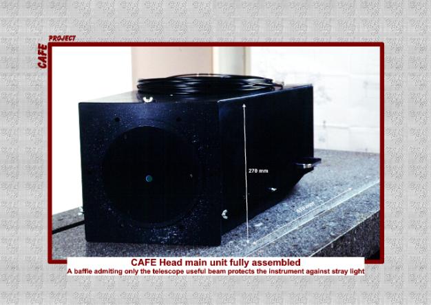
Figure 7 Picture of the CAFE Head fully assembled
The picture on Figure 7 shows the CAFE Head ready to be mounted on the telescope bonnette. It is completely blackened on the inside and outside and a baffle admitting strictly the useful F/8 telescope beam over the specified 25 arcsec field of view closes the entrance flange aperture. The protection cover can be opened at the back or easily dismounted in one piece to get full access inside the instrument for optical adjustment, parts replacement or fibre disconnection.
Figure 8 and Figure 9 give a presentation of how the elements are arranged inside the CAFE Head. These views show clearly that the instrument shape, dimensions and even structure have been mainly determined by the necessity to fit the huge and heavy LLLTV camera inside the volume. The calibration sources which are also implemented here are linked to the Central Optical Sub-Assembly (COSA) by way of a permanently installed fibre feed. These sources are isolated from the COSA by surrounding blackened walls forming a distinct calibration compartment inside the inner volume.
Figure 8 CAFE Head with Cover removed Mounted on Cass. Bonnette

Figure 9 Drawing top view of the CAFE Head
2.2.1 Central Optical Sub-Assembly (COSA)
The COSA is the sensitive part of the instrument with regard to optical settings and alignments. In this section its general and main features are presented while a more complete mechanical description can be obtained through the CAFE AUTOCAD drawing files. The procedure for the COSA optics alignment will be provided further on in the document at paragraph 3.1.
The next figures give a global opto-mechanical presentation of the COSA.
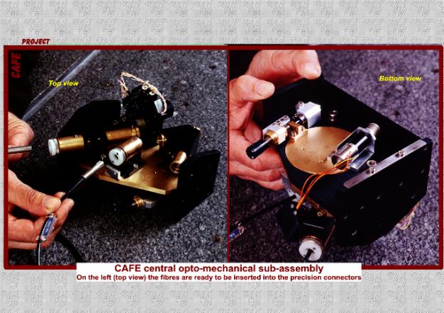
Figure 10 Pictures of the Central Optical Sub-Assembly (COSA)
The pictures in Figure 10 show the COSA dismounted from the CAFE Head main assembly. The top view on the left presents the Sky Fibre and the Calibration Fibre ready to be introduced into their respective connectors. The mounts supporting the Viewing and Calibration Optics can also be seen as well as the Mirror Wheel which permits the selection between telescope, flat field or wavelength calibration injections.
On the bottom view we can see the wheel stepper motor whose shaft is linked to the wheel axis by a cranked belt and the manual screw driven mechanism which commands the horizontal angular tilt of the COSA with regard to the telescope axis. On this view the fibres are connected onto the COSA.

Figure 11 COSA General Opto-mechanical Overview
This opto-mechanical drawing on Figure 11 shows the COSA implemented into its close environment in the CAFE Head main assembly. This view shows in particular the two orthogonal angular tilts f and q that can be applied on the COSA to permit the alignment of the Sky Fibre with the telescope incoming beam (respectively +/- 2.5 and 5 degree freedom). The rotation axis of the two tilts cross each other at the telescope focus which avoids the focusing variations on the fibre during the alignment procedure.

Figure 12 COSA general optical arrangement
The drawing in Figure 12 shows the general optical layout of the COSA stripped of all its mechanical parts.
The F/8 telescope beam is represented in red and green rays, respectively for the 1.85 arcsec field subtended by the Sky Fibre aperture and for the 25 arcsec specified for the acquisition field on the LLLTV camera.
A small fraction of the telescope incident light is deflected via a small silica window (Pick-up Window) towards the Viewing Optics to form an image of the telescope focus onto the micro-channel plate of the LLLTV camera.
On the other side of the telescope axis the Calibration Optics reconstruct with the light coming from the calibration sources via a dedicated fibre feed (blue rays) a F/8 beam for the Sky Fibre.
Switching from telescope to calibration injection is performed by way of a rotating wheel interposing mirrors and hole in front of the telescope central beam.
2.2.1.1 Viewing Optics
This part is designed to draw from the incoming F/8 telescope beam a weak percentage of the light and to form an image of the star object onto the micro-channel plate of the LLLTV camera. It is a very simple system constituted of two twin standard achromatic doublets and a flat folding mirror which are assembled together into a mechanical brass mount screwed into a fixed position on the COSA main frame when optically adjusted. A tilted silica window (Pick-up Window) is placed at the telescope focus at 0.43 mm in front of the Sky fibre entrance to pick up some 4% on the incident light through Fresnel reflection on its front face. Its rear face is A.R coated to limit the intensity of the twin image.
Main characteristics:
Input and output N.A: F/8
FOV: 3.5 mm
Working spectral range: 450 – 750 nm
Optics manufacture: Melles Griot standard
- doublets LAO 047 MgF2 coated
- folding mirror enhanced Al 02 MFG 014/023
- Pick-up Window: Sio2 window WLQ/S + A.R coating 078 on rear face (not in the Melles Griot catalog: dia = 5 mm thickness = 0.5 mm)
Mean transmission : 90%
More complete optical data can be found in the Annexe of the document at paragraph 10.1.1
2.2.1.2 Calibration Optics
This part is designed to reshape a F/8 beam for the Sky Fibre from the calibration light delivered by the flat field lamp and comparison source via a dedicated double line fibre feed (see next paragraph 2.2.2).
The optics, composed of two doublets of custom manufacture, were specified to yield a good correction as well as an efficient transmission over the 300 –1000 nm range which is well beyond the CAFE spectral coverage requirement. This demand was in fact justified and motivated by the possible use of CAFE in the UV below 400 nm where this facility could still be of some use for observation despite the sharp decrease of its fibre internal transmission in that range (see section 5).
The two doublets are fitted together into a mechanical brass mount which is screwed into a fixed position on the COSA main frame after optical adjustment.
Main characteristics:
Output N.A: F/8
Magnification: 2.96
FOV: 0.25 mm
Working spectral range: 300 – 1000 nm
Doublet manufacture: BaK2/FK54 MgF2 coated and cemented with Epo-Tek 305
Transmission @ 310 nm: 79 %
Mean trans. over 400 nm: > 95 %
More complete optical data can be found in the Annexe of the document at paragraph 1.1.1.
2.2.2 Calibration facility
This is the small compartment isolated from the main CAFE Head volume that contains the calibration sources which are optically linked to the COSA by way of a double line fibre feed.
The Calibration Fibre feed is using exactly the same kind of fibre and protection sheath as used for the Sky Fibre described above. Its mechanical terminations are also identical as those of the Sky Fibre but they come with no ancillary micro-optics. The Calibration Fibre cord is short, only 2 m long, and has been assembled according a Y shape arrangement as schematically shown on the Figure 13 below. It includes two identical fibres, one for the flat field halogen lamp and one for the comparison Th/Ar source whose output extremities are reunited together into the same termination with a centre to centre separation of 240 mm. This separation as small as it is has imposed however to implement two distinct mirrors on the rotating wheel that are specifically tilted to produce perfectly centred images on the Sky Fibre entrance.
Warning ! The two specialised input terminations of the Calibration Fibre cord must not be mixed up when inserted into their respective connector sockets. They are thus clearly labelled to avoid such confusion.

Figure 13 Calibration Fibre Feed arrangement
The Flat Field halogen lamp (ORBITEC H164615 12V-75W) is commercially provided with a small parabolic back reflector. There is no ancillary optics here since this simple design is sufficient to deliver a very sharp patch of light onto the Calibration Fibre tip input. A “cold” filter is however implemented in front of the fibre to prevent it from to much heating and a small blower is fitted behind the lamp to evacuate some of the heat away.
The wavelength comparison source is a classical Th/Ar hollow cathode source (ORIEL 3UAX/Th). A simple biconvex lens (Melles Griot 01LDX079) adapted at the tip of the source glass protection provides the necessary focussing onto the Calibration Fibre tip input.
2.2.3 Mirror Wheel
The Mirror Wheel is the only motor driven part of the CAFE system. It is the element that permits the selection between the telescope and the calibration injection towards the Sky Fibre but it also includes the opto-electronics devices for commanding and setting the instrument status.
It is presented by its AUTOCAD drawing on the Figure 14 below.

Figure 14 Drawing view of the Mirror Wheel
The wheel supports three mirrors and one hole distributed evenly around its periphery. The telescope beam is only allowed inside the CAFE Head when the hole is set in position on the optical axis and conversely, when interposed, the mirrors deflect the calibration beam towards the Sky Fibre input. The mirrors #1 and #2 are appropriately tilted in their lodging inside the wheel disk body so as to project centred images of the two distinct Calibration Fibre core outputs (Flat Field and Th/Ar respectively) onto the Sky Fibre aperture. A third mirror #3 is also adjusted for the Flat Field injection but it is covered with a neutral density of 2 meant to lower the degree of illumination for the LLLTV camera during the setting phase of the instrument (see paragraph 3.1).
The Mirror Wheel is activated by a PORTESCAPE stepper moto-reducer and its positioning is controlled by way of two RadioSpare EE-S infrared opto-detectors and also by an electrical switch (Wheel Switch) which provides at the same time a mechanical blocking detente and an electrical turn-off for the Mirror Wheel rotation.
The two photo-detectors and the detente switch are assembled together on a small fork mounting which can be easily dismounted from the wheel assembly and replaced by a complete spare in case of troubleshooting during observations. A second switch (Detente Switch) has also been implemented in the system to guarantee that the LLLTV camera remains inhibited whenever the mirrors #1 and #2 are on the optical axis.
A precise description of the Mirror Wheel organisation with its software correspondences is given in the Annexe at the chapter 8.2).
2.3 Gecko Interface
2.3.1 Mechanical design
The Gecko Interface refers to the small sub-assembly that comes at the end of the fibre link. It is a completely passive opto-mechanical assembly with no remote controlled element. It is designed to receive the Sky Fibre connector and the small image slicer meant to reshape the fibre output beam to the required characteristics for the spectrograph. Both fibre connector and image slicer are mounted together onto a precision linear and steering stage which is fixed on the adaptation flange for the Gecko entrance in the slit room. This small assembly is presented by its AUTOCAD drawing on the Figure 15 below and by the picture of Figure 16 taken during the photometric tests for the control of the output beam characteristics.
Figure 15 Drawing view of the Gecko Interface
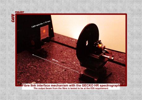
Figure 16 Gecko Interface under test for control of output beam N.A
2.3.2 Optical design
The optical characteristics of the Gecko interface are presented in the Figure 17 below.

Figure 17 Gecko Interface Optical Characteristic
The fibre-microlens system forms at the microlens focus an image that is in fact the far field of the fibre. This image is gaussian shaped and includes more than 95 % of the signal inside a 800mm diameter. It is then reshaped by the slicer into an elongated image 200mm wide and 3.2mm long. Placed at the Gecko collimator focus this four slice image becomes the entrance slit for the spectrograph and produces the required F/20 beam with an entrance pupil rejected at infinity (this entrance pupil is in fact the fibre core diameter seen through the microlens. This image is then reformed very enlarged onto the spectrograph grating).
The image slicer is of the Bowen-Wallraven type, all made of silica, assembled through molecular adhesion and designed to produce four slices (see Figure 18). Owing to the microlens, which transforms the fast fibre output beam into a telecentric and slow F/20 beam, no other optical element is needed and the system provided here for the Gecko entrance is thus very simple, compact, transparent and not subject to possible misalignments.
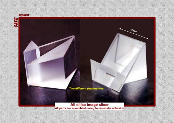
Figure 18 Views of the Bowen Wallraven Image slicer
3 Procedure for the Opto-mechanical Settings of CAFE
This chapter provides a step by step method for the alignment of the opto-mechanical parts in the instrument.
3.1 For the CAFE Head
Refer to Figure 9, Figure 11, Figure 12 and Figure 14.
The first two opto-mechanical settings a- and b- have been performed in the laboratory by the constructor before delivery. This preliminary phase is delicate but when completed should be permanent since all the concerned elements are then firmly blocked in position.
a- Optical conjugation between Calibration Fibres and Sky Fibre:
The conjugation of the two Calibration Fibre output apertures with the Sky Fibre aperture is obtained by tilting the mirrors inside their lodging on the Mirror Wheel and by the fine adjustment of the Calibration Optics.
The control is done by the analysis of the beam at the Sky Fibre output (maximum flux and clean photometric aspect of the fibre far field).
b- Opto-mechanical adjustment of the Viewing Optics
This operation consists in the fine alignment of the Viewing Optics and of the Pick-up Window with the incoming beams delivered by the Calibration Optics.
Simple control of the beam foot print with a small white sheet is enough to check that no vignetting is taking place along the optical path.
c- Setting of
the LLLTV camera
The Viewing Optics being correctly secure in position on the COSA, the LLLTV camera body can be now finely adjusted along the optical axis on its support rails by way of the screw provided at its rear side. The correct position is reached when the image of the Flat field Calibration Fibre output aperture (seen via the mirror #3) is at best focus on the camera.
From then on the following steps will be performed with the CAFE Head installed on the Cassegrain bonnette.
d- Optical
alignment of the Sky Fibre entrance with the telescope axis
This operation is important because any angular deviation between the telescope and fibre entrance axis will automatically be translated into an off-set of the telescope pupil image with regard to the fibre core. This will in turn generate some undesirable light losses. Accordingly the CAFE Head mechanical architecture has been designed to provide two degrees of rotation freedom on the COSA, f and q, whose orthogonal axis cross each other at the Sky Fibre tip location.
This steering adjustment of the COSA is performed manually owing to two counter-reaction micrometric screws. It is worth noting that this operation can be performed during day light (no consumption of overhead time) since all is needed is an image of the telescope pupil. Flooded dome, daylight or twilight illuminations are then perfectly appropriate here. The correct optical alignment of the Sky Fibre with the incoming telescope beam is obtained when the flux at the Sky Fibre output extremity is maximum.
It is worth noting that this operation will not upset steps a- and b- since the Calibration and Viewing Optics are mechanically linked to the COSA and its tilt adjustments.
e- Determination
of the Sky Fibre entrance address on the LLLTV camera
It is now necessary to determine the position of the Sky Fibre entrance on the LLLTV camera because it will be the only information provided to precisely target the telescope star image onto the fibre core.
Turn on the Flat field lamp and set the attenuated mirror M3 on the optical axis. Record the address of the barycentre of the image that is formed on the LLLTV camera array. This image happens to be also the sought address for the Sky Fibre entrance since Calibration and Sky Fibres have been previously conjugated through step a-.
From then on the opto-mechanical settings for the CAFE Head are completed .
3.2 For the Gecko Interface
Refer from Figure 15 to Figure 18.
As it is done for the CAFE Head, the Gecko Interface is delivered with a preliminary and permanent opto-mechanical setting. This step a- concerns the delicate adjustment of the image slicer with regard to the Sky Fibre output beam.
a- Image slicer setting
This operation aims to get a perfectly and evenly sliced image behind the slicer. When this is done the slicer is definitely blocked in position on its mechanical support.
b- Focusing and Beam steering
The Gecko Interface is now mounted on its adaptation flange in the slit room and the control of these last adjustments is done by analysis of the pseudo slit image focusing and orientation onto the Gecko CCD frame and by checking the beam path inside the spectrograph. The required high illumination level is conveniently obtained with the calibration Flat Field lamp set at nominal voltage and via mirror #2.
b1- with linear micrometric stage get best focus imaging on the Gecko CCD
b2- rotate Gecko Interface adaptation flange in order to get the pseudo slit image vertical and aligned with the Gecko CCD frame
b3- search for ideal beam orientation by fine adjustment of the Gecko Interface steering stage. When this is done check step b1- and b2- again.
4 Telescope Field acquisition and Tracking
Telescope field acquisition and tracking with the star image perfectly centred onto the Sky Fibre aperture is performed with the LLLTV camera and its Viewing Optics implemented in the CAFE Head. The signal is deflected directly from the incident telescope beam by the Pick-up Window positioned at the telescope focus.
This design gives access to a 25 arcsec field of view amply sufficient to ensure that the target star will be in the vision field after telescope pointing. Moreover, the brightness of the objects of interest for the Gecko programmes (m < 15) is high enough to permit in most cases the automatic guiding performed directly on the science star flux*.
Operation
procedure:
a- Send telescope to science star co-ordinates
b- Refine telescope pointing by centring the LLLTV star image onto the previously determined Sky Fibre aperture address. Finer targeting could still be obtained if necessary (especially at high air mass) by optimisation of the count rate of the Coude Exposure meter through one of the appropriate band-pass filters provided at this location.
c- When this is done the LLLTV signal is locked into a software box for automatic guiding
From then on there should be no other human intervention during the exposure time. If a suspect decrease of the exposure meter count rate is detected, one can then assume that some drift has occurred between the LLLTV camera and the Sky Fibre entrance (mechanical flexure ?). In that case resume steps b- and c-.
*Remark: if a programme is concerned with stars dimmer that m= 15 then automatic guiding directly on the science star may become inadequate. In that case it always possible to resort to the standard procedure making use of an off-set bright star and of the Cassegrain bonnette guiding camera. Of course in such situation it will be necessary to determine beforehand the Sky Fibre aperture address on the bonnette camera.
5 Instrument Efficiency on the Sky
5.1 Sky Fibre Link transparency
The optical path from telescope focus to Gecko entrance has been constructed to yield the highest transparency over the specified spectral coverage 400 – 1000 nm. The best materials and components have been selected while the optical coupling at the telescope/fibre link injection has been designed to collect 100% of the signal of a 1.85 arcsec image on the sky. It is schematically represented on the Figure 19 where the successive light attenuation sources are clearly identified on the associated table.
It is important to note that the total attenuation budget obtained with these theoretical figures fits very well to a few percents with the measures performed in the three B, V, R colours during the laboratory tests.
While the instrument is not specified to work below 400 nm it is nevertheless interesting to give its performance in that range:
at 310 nm, just above the atmospheric cut-off, the CAFE throughput is calculated to be around 20% (slicer not included), a loss of performance mainly due to the rapid decrease of the fibre internal transparency in the near UV (see Figure 3). Comparatively, at the same wavelength, the former Coude train in its UV configuration yields a 55% efficiency.

Figure 19 Photometric Attenuation Budget
5.2 CAFE versus Coude Train Overall Efficiency
The table in Figure 20 gives a comparative overview of the respective overall efficiency of CAFE and the former Coude train.
It is interesting to note that CAFE without the slicer compares quite closely with the global performance of the Coude Train from M3 to the Transfer triplet objective. Then CAFE benefits from the better efficiency of its Bowen Wallraven image slicer (about 90%) when compared to the former Richardson slicer (about 65%). However this advantage in then seriously counter-balanced by the CAFE important central obscuration produced by the camera optics in the spectrograph beam, a characteristic inherent to the loss of the instrument pupil shadow caused by the mode scrambling into the fibre (29% against 6% in the former Coude configuration).
So when everything is taken into account we can see that both configurations deliver approximately the same throughput onto the Gecko detector.
|
|
450 nm |
570 nm |
800 nm |
|
5 enhanced Ag mirrors (from M3 to M7) |
.78 |
.86 |
.89 |
|
SiO2 Field lens (2 air-glass MgF2 coated) |
.96 |
.98 |
.94 |
|
Triplet Objective (Bak5-CaF2 + multilayer coating) |
.97 |
.98 |
.98 |
|
Coude Train throughput (from M3 to Transfer Objective) |
73 % |
83 % |
82 % |
|
CAFE throughput (from Tilted Window to fibre output) |
79 % |
84 % |
84 % |
|
|
|
|
|
|
Coude
Train |
45 % |
51 % |
50 % |
|
CAFE |
51 % |
55 % |
53 % |
Figure 20 Comparison between CAFE and Coude Train Efficiencies
6 Component Maintenance
6.1 Spares
In the CAFE specifications it is required to supply the instrument with spares for all fragile or expected short life components. These items are listed in the table of the Figure 21 below along with their AUTOCAD file drawing index and the number of spares provided with the instrument delivery.
|
Drawing Index [Destination Index] |
Item Designation/function |
Spare Number |
|
51 |
Counter-reaction
button for COSA tilting micrometric screw |
2 |
|
50 |
COSA
tilting micrometric screw |
1 |
|
[51] |
Protection
cap for COSA tilting micrometric screw |
3 |
|
26 |
Fully
equipped opto-detector fork mounting |
2 |
|
58 |
Infra-Red Opto-detector |
6 |
|
73 |
Micro switch for Mirror Wheel stop |
4 |
|
59 |
Micro switch for LLLTV inhibition |
2 |
|
[25] |
Moto-reducer for Mirror Wheel |
1 |
|
56 |
Ball
bearer for Mirror Wheel shaft |
2 |
|
53 |
Cranked
belt for Mirror Wheel driving |
1 |
|
[19] |
Mirror
for Mirror Wheel |
2 |
|
40 |
Viewing
Optics mirror in its mount |
1 |
|
[14] |
Standard
achromatic doublets for Viewing Optics |
1 |
|
76 |
Pick-up
Window for Viewing Optics |
1 |
|
76 + 09 |
Pick-up
Window for Viewing Optics bonded on tilted mount |
1 |
|
17 + 18 |
Custom
manufacture doublets for Calibration Optics |
1 |
|
[37] |
Bi-convex
lens for Th/Ar source |
1 |
|
55 |
Th/Ar source + its female plug |
1 |
|
[49] |
“Cold”
filter for halogen lamp |
1 |
|
[78] |
Fan for halogen lamp |
1 |
|
54 |
Halogen
lamp + its
female ceramic plug |
3 |
|
72 |
Bowen Wallraven image slicer |
3 |
|
74 |
Sky Fibre cord |
1 |
|
75 |
Calibration
Fibre cord |
1 |
|
Electronics |
Connection cables (19” rack + manual command box) |
1 |
|
Logical card in 19” rack |
1 |
|
|
Power card in 19” rack |
1 |
|
|
Transmission card in manual command box |
1 |
This list is of course over-cautious and in fact once the instrument is installed on the telescope few risks are to be seriously encountered and feared especially if the Sky Fibre remains safely plugged into its connectors.
To be more specific with regard to the risks of failure probability, the components in the table are presented in different character style according to their degree of expected replacement frequency:
In italics => very weak probability of failure during instrument lifetime
In standard => 1 replacement may be expected “ “ “
In bold => to be replaced from time to time because of their normal limited lifetime
It must be noted that this last category belongs exclusively to the CAFE Head and their access here has been seriously taken into account in this assembly design.
6.2 Parts Replacement
6.2.1 Calibration sources
These are by far the parts that require the highest intervention frequency. Simple removal of the general protection cover provides easy access for their rapid standard replacement (maintenance time: 0.1 h).
6.2.2 Opto-detector fork mount
The standard replacement of that part requires to dismount the CAFE Head from the Cassegrain bonnette because it can only be reached from the CAFE Head front side aperture and with the baffle removed. Its dismounting is then easy since only one screw fixes it on the Mirror Wheel assembly (maintenance time: 0.5 h).
6.2.3 Moto-reducer and driving Belt
This operation can be performed with the CAFE Head in place on the Cassegrain port. Just remove the protection cover and release the two screws fixing the motor on its support (n° 25). It is the possible to remove the driving belt and proceed to the standard interchange.
To remove the motor from its support n° 25 it is necessary to dismount first the cogwheel from the motor shaft to get access to the screws. (maintenance time: 0.3 h)
6.2.4 Sky Fibre
The Sky Fibre has been routed from the Cassegrain environment to the Coude Slit room along with a twin spare and it can thus be readily replaced in a very short time should an accident occur or a degradation of the fibre throughput performances be noticed. Both fibre cords are by design identical but due to a slight difference on the microlens/fibre core centring between the two output extremities this fibre exchange will necessitate to re-adjust the alignment of the Gecko Interface Assembly with the spectrograph entrance (in order to optimise again the spectrograph illumination).
It is also clear that after such replacement all wavelength calibrations that may have been obtained previously are then invalid for the following exposures and should be performed again with the new fibre.
7 Electronics
7.1 Description

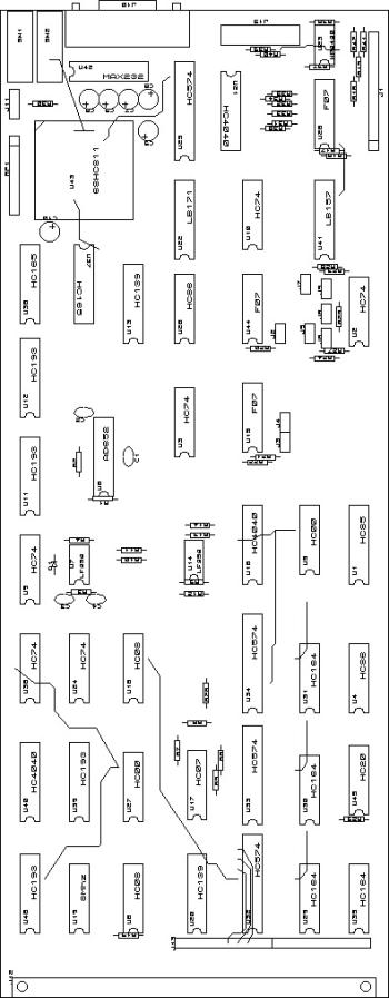
Figure 22 Electronics Main Parts Presentation

Figure 23 General Organisation of the Electronics Main parts
Figure 24 General Architecture Synoptic of the Electronics
7.2 Operation
7.2.1 General
Caution!
Avoid connecting/disconnecting any cable on the Electronics Rack while the power is ON. This may be destructive for the MAX 232 which is the first component on the Logical Card between the RS232 serial entrance and the micro-controller. This component acts in fact as a protection fuse and thus many spare MAX232 have been provided with the instrument to account for any possible wrong operation.
At start-up when the power on the electronics rack is turned ON the Mirror Wheel goes automatically to the Sky position (#3).
Actions or Querries on the instrument are then activated or asked by entering the command strings defined by the CAFE Logic Syntax (positioning of the Mirror wheel, switching On or OFF the calibration lamps and instrumental status. See table of Figure 28 )
7.2.2 About the Manual Command.
It is possible to operate CAFE by way of the Manual Command Box which provides the operator with labelled switches, buttons and panel lights (see Figure 25). The Box is linked to the Electronics Rack by way of a 12 m long supple cable.
How to operate:
- the Manual Command Box must first be turned ON by way of the upper central switch. The Mirror Wheel goes then automatically to the Sky position (#3). Remark that the ‘Wheel Stop Contact’ panel light is then turned ON indicating that the Detente Wheel Switch is correctly engaged in its notch. The G0 Encoder panel lights is ON while the G1 is OFF as prescribed by the CAFE logic
- to go to an other Wheel position, push one of the four black switches dedicated to each one of the Wheel positions and then push the red square switch at the top right of the front panel. This last action alone effectively launch the Wheel rotation. Remark that the ‘Wheel Rotating’ panel light is pulsing during the Wheel rotation while the ‘Wheel Stop Contact’ light is turned OFF
- when the Wheel has correctly arrived at the requested position the ‘Wheel rotating’ light is turned OFF while the ‘Wheel Stop Contact’ is turned ON again. If not, this is a sure indication that the Wheel is not exactly set at the requested position. The Encoder lights must also indicate the right binary combination in accordance with the CAFE logic
- it is also worth noting that the ‘LLLTV Inhibition’ panel light is either ON or OFF depending of the Wheel position (see sub-section 7.2.4.1 )
- the ThAr ON/OFF switch allows to activate the ThAr source. When it is ON its panel light is ON
- The two switches labelled ‘Setting FF Brightness’ allow to activate the Flat Field lamp. When it is ON its panel light is ON. By changing their combined positions it is possible to apply three different current levels to the lamp or to turn it OFF
- Remark: when either one of the ThAr source or FF lamp is ON, it is automatically turned OFF when the other is activated. The system cannot have both calibration sources ON at the same time

Figure 25 Manual Command Front Panel
If the Logical Card happens to be also linked to the outside computer via the RS232 when the Manual Box is connected to the Electronics Rack two cases must be considered:
- the On/OFF switch of the Box is ON (red panel light ON) => the RS232 connection is automatically interrupted
- the On/OFF switch of the Box is OFF (red panel light OFF) => the Box is deactivated and the normal operation of CAFE with the micro-controller via the RS232 can take place. In that case however it interesting to note that the panel lights on the Manual Box continue to give the actual status of the instrument (mirror Wheel position and status of the Wheel optos and of the calibration lamps).
In this situation if the Box ON/OFF push button is pressed ON again, the Mirror Wheel goes then automatically to the Sky position (#3) and the micro-controller sends the following character string: ?>V3VOK? >V .
7.2.3 About the Loading of the Control Program.
To load the program into the micro-controller one must apply a
reset order using the Reset Box as follows:
7.2.4 About Automatic Safety
The system is provided with two interlock securities in order to safeguard against too intense light flooding the two sensible photonics components of the CAFE-Gecko system, the LLLTV Camera and the Exposure Meter (E.M).
7.2.4.1 LLLTV Interlock
An output 5V bit allowing to inhibit the LLLTV camera when the Mirror Wheel is on either one of the two calibration positions (#1 and 2) is delivered at the BNC plug situated at the rear side of the CAFE Head sub-assembly. This signal bit is provided by way of the Switch Cam and via a small circuit placed on the inner wall inside the CAFE Head (see Figure 39).
7.2.4.2 E.M Interlock
The E.M situated at the entrance slit environment of the Gecko is by far the most fragile component and was as such fitted with 2 interlocks.
- a first one is provided with a 5V bit inhibiting both the calibration lamps in the CAFE Head. This signal is electro-mechanically triggered by way of the E.M shutter close or open position.
- A second one is provided also by a other 5V bit signal which this time prevents the opening of the E.M shutter by activating a relay closure when either one of the two calibration lamps is ON.
8 Control Program and Logic Syntax
8.1 Control Program Upper Level Flow Chart
The Control Program is organised around two distinct parts:
- the Main Loop and
- three Functions (Mirror wheel, Lamps and Status) which are called according to the command character that is received in the Main Loop;
The Main Loop has been solely programmed for
- waiting and receiving the characters sent via the RS232 link
- checking if these characters fit one of authorised commands (w, s, f or t) and if this is the case, calling the function associated with it. If not, a message “E_CMD” is emitted via the RS232.
Concerning the other characters corresponding to a parameter or at a <CR> for the Querries, this is taken in charge by the Function itself, so outside the Main Loop. When the Function is completed the program goes back at the top of the Main Loop waiting for a command character.
The Main Loop and the three Functions flow charts are presented below by the diagrams of the Figure 26.


Figure 26 Upper Level Flow Charts of the Control Program
8.2 Program Logic Syntax
|
Commands/ Querries (what you type) |
Echoes (of what you typed) |
Responses (after successful action) |
Remarks |
|
wØ# |
w·Ø#¤ |
#·OK¤ >· |
# is
one of the 4 Wheel positions: Ø; 1; 2; 3 |
|
w¤ |
w·¤ |
#·OK¤ >· |
|
|
wØ# |
w·Ø#¤ |
#·OK¤ >· |
# is
one of the 8 intensities for the FF: Ø; 1; 2; 3; ….7 |
|
f¤ |
f·¤ |
#·OK¤ >· |
FF
lamp |
|
tØ# |
t·Ø#¤ |
#·OK¤ >· |
# is
Ø; 1 for the ThAr (Ø is OFF and 1 is ON) |
|
t¤ |
t·¤ |
#·OK¤ >· |
ThAr
source |
|
s¤ |
s·¤ |
PO·#¤ |
# is
one of the 4 wheel positions: Ø; 1; 2; 3 |
|
|
GØ=>
ON or OFF¤ |
Opto
left (see figure) |
|
|
G1=>
ON or OFF¤ |
Opto
right (see figure) |
||
|
SW=>
ON or OFF¤ |
Wheel
Switch |
||
|
SC=>
ON or OFF¤ |
Camera
Switch ** |
||
|
MO=>
ON or OFF¤ |
Wheel
Motor |
||
|
F=> #¤ |
# is
Ø; 1; 2;…;7 for the FF (Ø is OFF) |
||
|
T=> #¤
>OK¤>· |
# is
Ø; 1 for the ThAr: (Ø is OFF and 1 is ON) |
||
* => Cde Lamp ON (ThAr or FF) turns OFF automatically the other one if ON
** => ON enables LLLTV
|
ERRORS or Failures |
|
|||
|
Commands |
Echoes |
Responses |
Remarks |
|
|
wØ5 |
w·Ø5¤ |
#·E_OVER¤ >· |
Bad
Cde. Goes for W, f or t # is the present status |
|
|
b |
b¤ |
E_CMD¤ >· |
Unrecognised typo |
|
|
tØ1
or fØ1;..; Ø7 |
t·Ø1¤ or f·Ø1;..; Ø7¤ |
E_TIME·OUT¤ >· |
No
current in lamp (In Status => OFF) |
|
|
wØ# |
w·Ø#¤ |
#·E_TIME·OUT¤ >· |
# is
the wheel sector in position at wheel stop |
|
Figure 27 Table of the Logic Commands, Queries and Errors

|
Position
Ø => Dimmed F.F Mirror |
Position
1 => F.F Mirror |
|
GØ = ON G1 = ON SC= ON |
GØ = OFF G1 = ON SC = OFF |
|
Position
2 => ThAr Mirror |
Position
3 => Sky Mirror |
|
GØ = OFF G1 = OFF SC = OFF |
GØ = ON G1 = OFF SC = ON |
Figure 28 Mirror Wheel Opto-Electrical-Logic Relations
Remark:
9 Commercial Part List
On Figure 29 are given the references of the commercial parts in CAFE with the co-ordinates of the manufacturers or suppliers.
|
Drawing Index [Destination Index] |
Item Designation |
Manufacture/ Supplier |
References |
|
51 |
Counter-reaction button |
SUPRATEC |
HWN
207 |
|
50 |
Micrometric
screw |
NEWPORT |
AJS
0.5 |
|
[51] |
Protection
cap |
NEWPORT |
AJC
0.5 |
|
70 |
Mirror
mount |
NEWPORT |
MFM100 |
|
71 |
Micrometric
Linear stage |
NEWPORT |
M-UMR.5/16 |
|
58 |
Infra-Red
Opto-detector |
RADIOSPARES |
(EE-S)
219-2498 |
|
59 |
Micro
switch (interlock) |
RADIOSPARES |
(Cherry)
665-972 |
|
[25] |
Moto-reducer |
API Portescape |
P110
064 2.5 12 R16 0166 |
|
56 |
Ball
bearer |
SCIAM |
SKF
618/15 |
|
53 |
Cranked
belt |
Binder Magnetic |
8.T2,5/145 |
|
[19] |
Mirror
(Mirror Wheel) |
MELLES GRIOT |
01MFG
023/023 |
|
40 |
Viewing
Optics mirror |
MELLES GRIOT |
02MFG
014/023 |
|
[14] |
Doublets
(Viewing Optics) |
MELLES GRIOT |
LAO047 |
|
76 |
Pick-up Window |
MELLES GRIOT |
02WLQS
AR/078 1 face |
|
[37] |
Bi-convex
lens (Th/Ar source) |
MELLES GRIOT |
01LDX079 |
|
17 + 18 |
Doublets
(Calibration Optics) |
OPTICAD |
none |
|
55 |
|
ORIEL |
3UAX/TH |
|
[78] |
PAPST
Fan (halogen lamp) |
FARNELL |
151-270 |
|
54 |
Halogen
lamp |
FRANCO BELGE |
ORBITEC
H164615 |
|
72 |
B.W
image slicer |
OPTICAD |
none |
|
|
|
|
|
|
Electronics |
Connection
cables |
J.Tronic-S.A.R.L |
none |
|
Electronic
cards |
ATLANTEC |
none |
|
|
Hollow
cathode Power supply |
ORIEL |
C610-B2 |
|
|
12
V 100 W Power supply |
FARNELL |
253-390 |
ATLANTEC Z.I de la Croix Blanche 44260 Malville 33-240 56 45 44
API
Portescape 2 Rue Louis Pergaud 94706 Maisons Alfort
33-145 18 33 93
Binder
Magnetic 1 Allée des Barbanniers 92632 Gennevilliers
33-146 13 80 80
FARNELL
France 754 Avenue de l’Europe 69400 Villefrance 33-474 68 99 66
FRANCO
BELGE 5 Avenue Jules Ferry 92245 Malakoff
33-141 17 34 34
J.Tronic-S.A.R.L 31 Rue des Petits Ruisseaux 91370 Verrières 33-169 53 94 00
MELLES
GRIOT 1 Rue Guynemer 78114 Magny 33-130 12 06 80
NEWPORT 3 rue Jean Mermoz 91006 Evry 33-160 91 68 68
OPTICAD 9 Rue Léon Foucault 77295 Mitry-Mory 33-160 21 00 64
ORIEL 9 Avenue de Laponie 91951 Courtaboeuf
33-160 92 16 10
RADIOSPARES Rue Norman King BP 453 60031 Beauvais 33-344 10 15 45
SCIAM 15 Route des Gardes 92193 Meudon 33-145 34 61 71
SUPRATEC Rue Charles de Gaulle 91070 Bondoufle 33-160 86 42 51
Figure 29 Commercial Parts List and Suppliers/Manufacturers co-ordinates
10 Annexes
10.1 Optical data
10.1.1 Viewing Optics