Room 412A - 4th floor - NESLAB COOLER CHECK-OUT
- Clearance of 2 ft on three sides of NESLAB cooler.
- Glycol level 1" below top of reservoir - covering coils. Look under
metal plate located on the top left corner of the unit.
- Make sure the power switch of the cooler is on. NOTE: Unit will
not turn on until power is applied in step #5.
Room 412 - 4th floor - NESLAB COOLER POWER START UP
- Verify input power on wall panel to NESLAB and both lasers.
(Green light indicator next to "emergency shut off" button is
illuminated). This panel is located next to the lab entrance
door.
- Push top green button of the power panel to turn the NESLAB cooler
on. (Green light will illuminate).
Room 412A - 4th floor - NESLAB GLYCOL CHECK-OUT
- Glycol flow at 4.2 gpm. It will be at >5 gpm at first. (Look at
the float in the transparent column of the glycol flow-meter
on right side in the lower right corner of the unit).
NOTE: Flowtec switch on LAMA requires minimum 2 gpm.
- Glycol pressure - meter at 42 psi. (Pressure meter on right side
in the lower right corner behind heat vent).
- Set point temperature = 15C (+/-2C). (Front panel of Neslab cooler).
Press button to read.
Room 412 - 4th floor - LASER START UP AND OPERATION
Power Start Up Sequence
- Push the second button of the power panel to supply the electronics
rack of LAMA I. (Green light will illuminate). This is needed
for computer control of the laser gating signal.
- Push the third button of the power panel to supply the electronics
rack of LAMA II. (Green light will illuminate).
Electronics Rack Diagrams
Below are two full diagrams of the electronics racks from which selected items
will be referred to. These diagrams will allow you to find the specific
electronic instrument panel within the entire electronics rack.
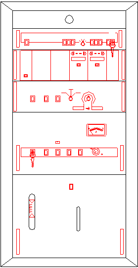
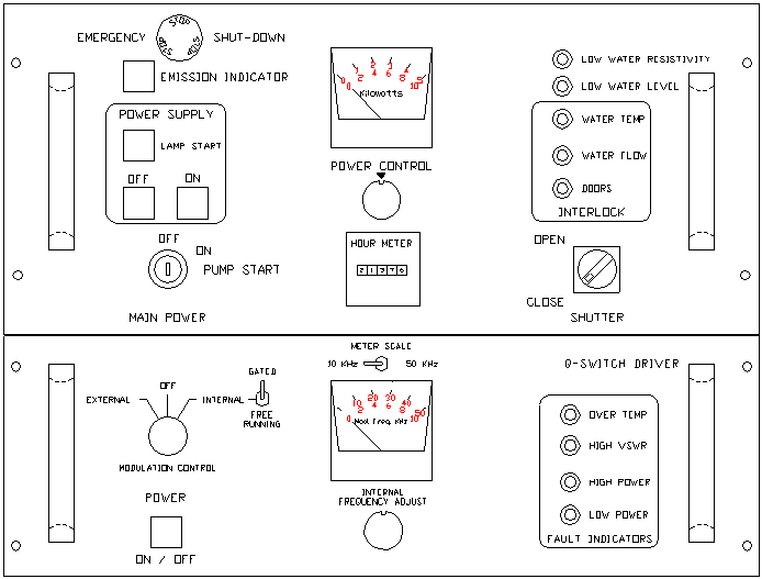
Computer Interface (IP28) Start Up (Top unit of control rack)
Refer to figure 1 below for steps 11 through 14 for locations of IP28 key
switch and power button.
- Set IP28 computer interface to local mode ("L") with the 1/4 turn
key switch located on the right side of the unit BEFORE
applying power.
- Turn on IP28 power - "secteur" push-button switch located on the
left side of the unit (button will illuminate).
- Set IP28 to distance mode ("D") using the same key switch on the
right.
NOTE : Do not apply power to any other component in the LAMA I rack.

Figure 1.
Laser Optical Pump Lamp Power Supply Start Up
NOTE: Whenever the Yag laser is to be used for cutting, the laser safety
shield must be closed or protective eye-wear - laser goggles - must be worn
by all personnel in the room AT ALL TIMES.
There are 2 lasers in the system. A red HeNe laser (wavelength 632.8 nm) -
which should be visible as soon as the switch is turned on and the shutter is
open - indicates the location of the cutting beam. The infrared YAG laser
(wavelength 1.06 microns) - the high powered beam which does the cutting - is
INVISIBLE. Its presence will generally be noted however by the white-hot spot
it creates as it cuts the metal masks. The YAG beam should only be present
when: i) the lamp power is turned up, and ii) when the cavity shutter is
opened. But be careful. Don't assume that these conditions exist.
- Before applying any power to any component in LAMA II rack, turn
the POWER CONTROL knob fully counterclockwise and the SHUTTER
switch to the CLOSED position. See figure 2 below for power
control knob and shutter switch location.
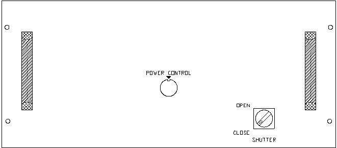
Figure 2.
- Turn on the HeNe laser with the white power cord switch located on
the left side of the X-Y stage. Note that the HeNe laser will
not be seen until the electronics rack is turned on, the pumps
are running and the shutter is open.
- Turn the main power key switch of the LAMA II top rack to the on
position. The EMISSION INDICATOR and WATER FLOW interlock
lights should be illuminated. The cooling pump should not be
running at this time. Wait at least 10 seconds before
proceeding to step 17. See figure 3 below for location of key
switch.
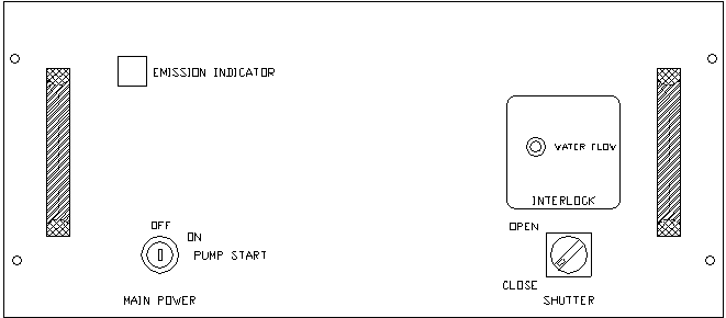
Figure 3.
Before turning on the power supply to the lamps, check the operation of the
safety shutter. Open the shutter by actuating the SHUTTER OPEN/CLOSE switch.
Note that the HeNe laser now comes through the system and the red light
on top of the laser unit is lit. Close the shutter and note that the HeNe
laser is blocked off. IT IS IMPORTANT THAT THE SHUTTER REMAIN CLOSED
DURING THE REST OF THE POWER UP SEQUENCE.
- Turn the main power key switch to the PUMP START position and hold
it momentarily until the pump starts. Release the key and it will
return to the ON position. The WATER FLOW indicator light should now
be OFF.
- Push the POWER SUPPLY ON button to turn on the power supply. The
POWER SUPPLY OFF indicator should go off, and the POWER SUPPLY ON
indicator should light. Note: the power supply will be shut down if
the RIC interlock circuit is opened while the power supply is running.
(Interlock is currently not implemented and RIC is shorted at this
time.) See figure 4 below for the location of the power supply on
button and the lamp start switch indicator.
- The LAMP START indicator should gradually light in 30 seconds
indicating that the capacitors are fully charged. You MUST wait these
30 seconds before firing the lamps.
- Press the LAMP START switch to fire the krypton arc lamp. The LAMP
START indicator should go off, and the lamp power meter should come up
to an idle power level of about 2.2 Kilowatts as read on the upper
scale.
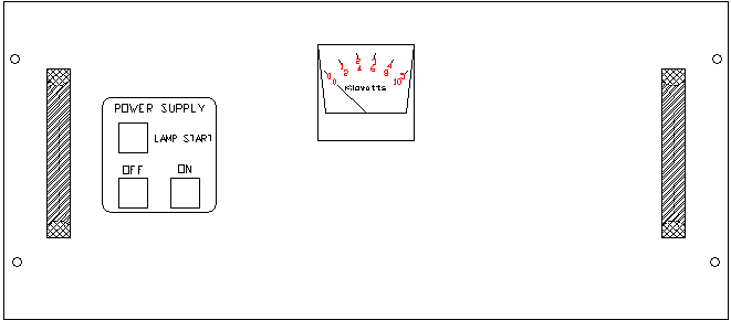
Figure 4.
- Set the power level to 3.0 Kilowatts by rotating the POWER CONTROL
knob clockwise while observing the power meter reading the upper scale.
See figure 5 below for power control and power meter locations.
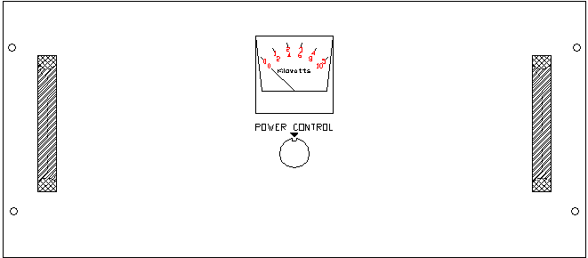
Figure 5.
NOTE: Laser output is not optimized at this time; it may take at least
20 minutes of system warm-up time, but you may begin cutting
immediately after turning on the Q-switch in the next section.
The emission indicators should be on. There is one on the rack and
one on top of the laser unit (a yellow light).
Q-Switch Driver Start Up
- Press the ON/OFF push-button switch; the ON indicator in the switch
should light. The LOW POWER fault indicator light may come on for about
15 seconds while the system is charging up the capacitors.
- Make sure that all FAULT INDICATOR lights are off before proceeding.
See figure 6 below for ON/OFF switch and fault indicator light
locations.

Figure 6.
For steps 24 through 26 see figure 7 below for MODULATION CONTROL KNOB, FREE
RUNNING/GATED TOGGLE SWITCH, INTERNAL FREQUENCY ADJUST KNOB and METER SCALE
locations.
- Set the MODULATION CONTROL KNOB to the INTERNAL position and the
TOGGLE SWITCH to the FREE RUNNING position.
- Adjust the modulation frequency, if needed, to 2.0 Kilohertz by
turning the INTERNAL FREQUENCY ADJUST KNOB while watching the meter
scale.
- Now flip the toggle switch to the GATED position. THIS MUST BE
DONE OR LASING WILL BE IMMEDIATE AND CONTINUOUS AS SOON AS
THE SHUTTER IS OPENED.
Note: the frequency meter scale will read 0 KHz until the computer
program turns the modulator on as needed.

Figure 7.
Computer Initialization
Refer to the LAMA software control document for a more
explicit description of the following steps.
- Turn on the Gateway 2000 computer if it has been turned off and
allow it to boot up until you have a desktop with various icons
displayed.
- Double click the Netscape icon and let the LAMA Conversion
Utility program start up.
- In the text window, type over the example the name of the file
you want to convert.
- Click the CONVERT button and check to see that there are no errors.
Iconize Netscape for later use with the "-" button in the upper right
hand of the Netscape window. The program is now immediately available
on the "task bar" at the bottom of the screen. Clicking this will bring
up the conversion program.
- Double click the CUT MASK ICON and find the converted file as a
"filename.dmc"
NOTE: the truncation in the filename is normal. This
window also can be iconized for later immediate use.
You can
Click here  for a demonstration of
the LAMA Conversion Utility program.
Focussing TV Camera Set-Up
- Turn on the Video X-Y Cross Hair generator and the video monitor
located above the LAMA II electronics rack. Turn on the high intensity
lamp located near the X-Y stages. With the light directed at the laser
cutting point from the front, and the main focus control properly set,
a magnified image of the foil should appear on the monitor with the
aligned cross hair target when the stages move the foil under the
laser focal point.
If no image appears then check power cords from both the camera power supply
and the monitor. Also check that the BNC signal cable from the camera goes to
the Colorado Video cross hair generator input on the back and that a BNC goes
between the Colorado Video cross hair generator output to the monitor input.
When Ready To Cut Masks
- Set mask holder securely into X-Y stage. Note: the mask frames must
be mounted with the registration pin cutout to the back right corner
of the vise.
- Check the laser lens focus. Focus is adjusted with the large
micrometer head visible at the front of the YAG laser. Focus values
for mask cutting are as follows:
                    MOS       50.95
                    OSIS      43.60
Focus values for cutting mask blanks using the `platform' are:
MOS or OSIS 37.00
-
- Open SHUTTER SWITCH to the OPEN position. Red light on top of
laser indicates that shutter is open.
- Turn on the vacuum switch if desired. The switch is located to the
left of the focussing monitor above the electronics rack.
To Cut Masks
- Double click the "filename.dmc" icon in the cut mask window. The
stages will initialize themselves and then cut the requested mask. Look
at the Gateway computer for feedback.
When Mask Cutting Is Completed
- close cavity shutter by turning the shutter switch to the
CLOSE position.
- turn lamp power down to 2.2 Kilowatts.
- turn off vacuum switch.
Mask Cutting Trouble-Shooting
The most common problem in cutting masks is that some or all of the apertures
are not cut cleanly. If all the apertures are not cut properly, it is most
likely that the focus control knob is off by +/-1 rotation from the nominal
focus position. Rotate the knob a long ways off until you are sure where you
are and then go back to the focus position and try again.
If only some of the apertures are not cut cleanly, examine the density of the
apertures within the mask. If too many apertures are cut close together, local
heating from the cutting process may warp the mask material enough to take it
out of focus. In this case, reduce the power to 2.6 or 2.5
Kilowatts and increase the number of passes taken around each aperture.
Shutdown Procedure
- Follow these steps to shutdown the LAMA system:
- Turn off the Q-SWITCH DRIVER by pushing the POWER ON/OFF
switch noting that the light goes out.
- Set the POWER CONTROL knob back to minimum power.
- Press the POWER SUPPLY OFF button to turn off the power
supply.
- Allow the water pump to run for 2-3 minutes, before turning
the main power key switch off, to prevent thermal shock damage
to the laser crystal.
- Turn power off on the IP28 module.
- Turn off NESLAB cooler power and LAMA I & II power in room
412 by pushing the emergency shut off button on the bottom of
the power panel.
- Turn off the HeNe laser switch located on the left side of
the system.
- Turn off both the Colorado Video cross hair generator and
the associated monitor.
- Turn off vacuum switch if necessary.
 The CFHT LAMA II (ser chine)
START UP CHECKLIST AND MASK CUTTING MANUAL


