


This section gives practical guide-lines for conducting observations with SIS. Observing recipes summarize the recommended procedures for imaging, long-slit and multi-slit observations. The different steps are then separately presented and discussed.
SIS is easy to use and reconfigure. However, this flexibility necessitates vigilance on the part of the observer to assure correctly set observing parameters and to properly conduct an observing sequence. Recommended observing steps are given below. These have been developed from extensive experience, and have been proven to be the most efficient procedures. We suggest that you do not try to take short cuts or innovate too much in the fallacious hope of saving time. The basic recipes are, in fact, not very difficult. The most complex sequence of observations with SIS (i.e. in its long slit or multi slit mode) can be divided into 10 successive steps for a given field:
Below is a condensed summary of the sequence of actions recommended to take direct images with SIS.
Below is a condensed summary of the sequence of actions recommended to take long-slit or multi-slit spectra with SIS.
The Cassegrain Environment, containing the Cassegrain bonnette (with guide probe, etc.), the entire MOS/SIS assembly, as well as auxiliary and support equipment, can be rotated to allow any position angle on the sky (the ``bonnette angle''). Rotation of the Cassegrain environment is controlled by a hand paddle in the control room. Ask the support astronomer or the T.O. for assistance.
Bonnette rotation with SIS should be carefully considered in spectroscopy mode. A single step of the bonnette rotation encoder is 0.05 degree, hence the repositioning accuracy could be, in principle, of the order of two pixels over 2048 pixels on the CCD. In fact, because of mechanical inertia, it is quite difficult to stop at a given position angle with this degree of precision. Moreover, tests conducted in February 1995 show that, for two images taken with identical readings of the encoder, the residual rotation can amount to 0.2 degree. This is likely a more realistic value for the rotation accuracy and corresponds to about 7 pixels over a 2048 pixel field, or 0.6".
This is not a problem if the alignment of the aperture mask with the object field can be done within these tolerances; however, if a mask is to be used over several nights, we strongly urge that a single position angle be maintained for all fields to be studied during this time. On the other hand, it may be appropriate to use position angles chosen for each individual field, to allow selection of guide stars so as to minimize occultation by the guide probe. In this case, we recommend that the entire procedure, from direct imaging, to mask creation, to the spectrographic exposure, be completed for a given field before rotating the cassegrain environment to a new bonnette angle.
The situation is less critical for programs involving imaging only.
For field acquisition, we recommend the following steps:
Once your object is seen on the CCD, any further offset is better done with the OFFSET procedure and, for precise centering of objects into the slits, with SIS-Ofst (see section section 5.4 and section 6.7).
With SIS the focus must be done accurately to take full advantage of the active guiding, and it is wise to check it for each new field or, if the outside temperature is varying rapidly, before each exposure. The most efficient method for focussing is to use CAF (see section 5.3 and hereafter).
Because of vignetting in the pupil plane by the bi-prism system, the light is reduced by a factor of more than 10 when using CAF, with respect to direct imaging. We also need a sufficient S/N for an accurate estimate of the star's centroid with typical 10 - 20 s exposures. This means that appropriate focus stars should have V magnitudes between 12 and 14.
N.B.: CAF uses the iqe function for computing the centroids of the images. The next time you open the iqe window, you will have to change the file name back to ``current.fits'' as well as the parameters (activate fwhm and other options).
If you like to spend a lot of time performing a focus or if, for any reason, CAF is not available when you are observing, you can focus the telescope manually.
To do so use a focus star of magnitude 14 - 16 and take successive exposures (with at least 10 s exposure times), changing the telescope focus with the handpaddle by steps of 5 telescope focus units between
each exposure. Using IQE, compute various image parameters for each exposure. The image statistics of importance are the FWHM's of the image along the X and Y axes (or along minor and major axis of the best fitting ellipse) and the maximum (peak) value. To be
in perfect focus, you need (i) a perfectly symetrical image on the
display monitor, (ii) X and Y FWHM's as small as possible and as
identical as possible, (iii) a peak value as high as possible.
This function (see section 5.4) is for offset motions up to a few arcmin with Cass bonnette guiding. It can be used for centering objects in the slits (but, at this stage, you will probably use SIS-Ofst if the active guiding is on) or for sending a guide star to a given location, eventually outside the CCD.
This performs a function similar to the above offset but with active guiding. It will move the SIS guide probe and then the telescope in order to keep the guide star centered in the probe. SIS-Ofst is used mostly in spectroscopic mode for accurate centering of the objects in the slits. Be careful not to reach the limits of the guide probe motion in the process. If you use the same guide star for the spectroscopic exposure as for the imaging exposure used to define the mask, there is very little chance for this to occur.
Although you will probably prefer to use the active guiding system provided with SIS, it is also possible to guide with the Cassegrain bonnette, i.e. without image improvement. This could be the only choice for (very rare) ``empty'' fields down to magnitude 18 or in case of heavy atmospheric absorption that reduces the limiting magnitude (hopefully, also a rare circumstance). In such special cases, the Cassegrain bonnette can search for a guide star in a larger field. This is also the normal procedure for taking centering exposures and for keeping good telescope tracking while you are searching for your guide star with the SIS probe.
The T.O. is normally in charge of moving the Cassegrain probe until a suitable star is found. He usually records the XY position of the Cass bonnette, as well as the XY position of your star on the guiding TV. This will save a lot of time for centering if you plan to come back to the same field on a subsequent night, as it will ensure that the telescope is on the same location on the sky. The reproducibility of the recentering is a few pixels.
Here is the procedure for active guiding in either imaging or spectroscopy mode:
This assumes a dark sky (level around 3000 counts/s); during grey time, use longer integrations to obtain the same S/N.
A direct imaging sequence with SIS proceeds as follows.
The sequence is similar to direct imaging, except that you should have centered your objects in the slits with SIS-Ofst and chosen a grism.
When taking several long exposures of the same field, we recommend that you check the position of the reference star(s) with respect to the mask between each exposure, since instrument flexures, although small, are cumulative. Such a check does not take a long time if you use a sub-raster around your reference star.
Once an image of your field has been acquired, you can process it to prepare the mask. This is done on another HP terminal with the LAMA account (login: lama; same password as the SIS data acquisition account).
The Lama session manager menubar with its accompanying icons is displayed
(figure 6.1).


First select the setup form (figure 6.2). It asks for the instrument in use (MOS or SIS) and for the CCD name (the important parameter here is the pixel size; it is automatically recognized from the name of the device). This will set the scale (i.e. the correspondance between pixels and arcsec.) for the mask design.


Then, select the Grism ENG form (figure 6.3) and give the grism identification and parameters of your spectra: i.e. the central wavelength and wavelength range you want to cover. This will set the limits of spectra that will be overlaid on the field image when you select your objects. This is useful for defining the area of full wavelength coverage, or when you want to cut two or three series of slits per column with low dispersion grisms and/or wavelength range limited by a pass-band filter. However, be aware in that case that zero order images of the slits corresponding to a given series could fall on the spectra of another series.


To design a mask, select lama mask in the menu bar. The form (figure 6.4) will require the following inputs from you:


The LAMA cutting machine is now located on the fourth floor. Here you should find the number of mask-holders and blanks that you requested. Using the machine is quite easy. Just follow the detailed check-list for starting the machine in the LAMA manual which should be found near the machine. Ask your support astronomer to be present when doing it for the first time. When everything is ready, enter the YAG file name on the terminal (299742o.l0y in our example).
Cutting time depends on the number of slits to be cut, their size, and on the number of passes made with the laser. This parameter can be adjusted in the cutting program, but the default number is four passes and normally produces very clean cuts. If, for any particular reason, you want to change this parameter, ask the support staff in advance.
After finishing the mask cutting for the night do not forget to shutdown the LAMA following the procedure in the manual.
Mounting the mask-holders in a mask slide is quite easy and it is not possible to mount them with the wrong orientation. It is more efficient to mount several new masks at the same time in an empty mask slide and exchange the mask slides on SIS. During this step, make sure that there is no misidentification of the masks: note the mask names for each position in the slide.
To remove the mask slide from SIS, first, in the control room, send the mask slide to position 1 (open) with the SIS procedure. In the dome, remove the octagon cover (pull radially on both handles, then rotate), and the completely unscrew the SIS slide screws, while supporting the mask slide with one hand. N.B.: it is important to unscrew totally, even if it seems that the slide can be removed before that. It is obviously also quite important to prevent the mask slide from falling on the ground! Remove the old mask slide and insert the new one, pushing it all the way up. Screw the SIS slide screws completely in again, and replace the octagon cover. (The latter might be the most difficult step if you are not used to it). Back in control room, first enter the new mask identifications in the SIS form. Then send the mask slide to the position of one of the masks and take a direct image with the halogen image lamp. This will allow you to compute the offset needed for centering the objects in the slits.
To adequately calibrate direct imaging data you need the following auxiliary files: flat fields of the dome or sky, bias frames, and photometric standard frames. These frames should be obtained with the same raster and binning as the science frames.
Table 6.1 gives exposure times needed to obtain a flat-field level close to 15000 ADU with Loral 3 when using the top ring lamps. Adjust your exposure times as needed for other filters. Take several exposures and average them later.

See the documents in the control room for a list of photometric sequences and finding charts. These lists and images will hopefully also be available on-line in the near future. Typical exposure times are 20 to 90 s, depending on the field and the filter (longer exposures for bluer filters). It is best to have data on two fields at different air masses for extinction corrections.
With the present CCDs there is no significant difference between biases and darks. Take several biases and if desired use the ``combine'' option.
Spectroscopic data are calibrated in wavelength by using the bonnette calibration lamps unit and in flux by obtaining spectra of spectrophotometric standard stars. To calibrate your spectroscopic data you need the following: biases, spectroscopic flat fields, wavelength calibration spectra and spectrophotometric standard spectra. All frames should be obtained with the same binning and raster as science frames. Do not forget to select ``comp'' in the exposure window when you want to use lamps in the calibration unit.
These are obtained from a spectrum of a quartz lamp (in the bonnette calibration unit) with the same combination of aperture mask, filter and grism as the science frames. A typical exposure time is 10 sec with the ``Halogen spectrum'' lamp.
The situation with the present set of spectral lamps is not optimal and this is likely to be changed in the future. Table 6.2 lists exposure times that give the brightest lines signal levels close to saturation (32767 ADU) with 1.0" slits.

One will note some prohibitively long exposure times are needed for the B600 and, especially, the U900 grisms. Moreover, the distribution of the lines with wavelength is not particularly good for these two grisms, but is better for the others.
Spectrophotometric standard stars can also be found in documents in the control room (and on-line in the future). A typical exposure time is 1 to 5 min, depending on the star you choose and the grism you are using. You may want to use a wide (3") slit for better spectrophotometric calibration or use the same slit width as for your science frames.
The CAL-SEQ procedure is useful for automatic calibration in spectroscopic mode. Direct images of the mask, spectral calibration and spectroscopic flat-field exposures can be programmed for up to three masks (see figure 5.11). For flat-field exposures, a number of iterations should be requested; the result is the average (with cosmic ray hits removed by sigma-clipping) of these iterations. It is not recommended to use more than 10 - 20 iterations, first because of the amount of time it would take and also because of a possible failure of the averaging process.
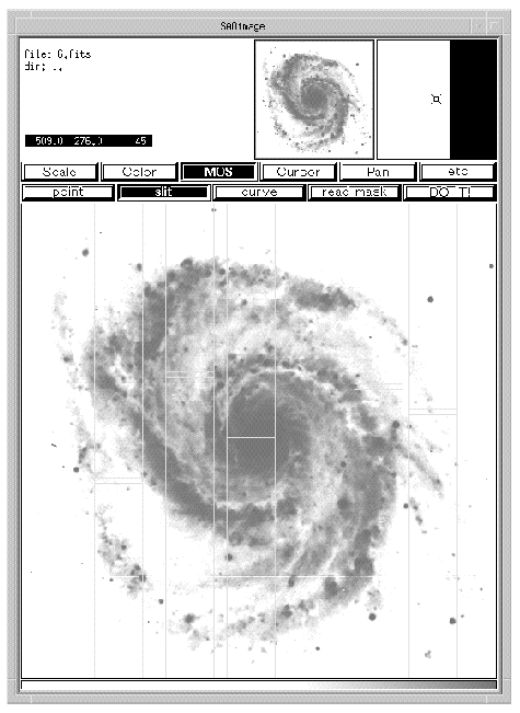
The IMAGE form (figure 6.6) permits a grey scale display of a selected image. If the image name in this form is ``current.fits'' the last image transferred to the disk will be displayed. Normally, it appears automatically in the SAOIMAGE window as soon as the reading of the CCD and the transfer to the disk are over. If it does not, open the ``MODES'' icon and select automatic image display.
The IQE form allows for the computation of various statistics on a FITS file, such as the mean, standard deviation, and minimum and maximum values. It can also give a good estimation of the image quality. Select a non-saturated but bright star and a box size at least 20 pixels wide. The spatial indications returned by IQE (FWHM, centroid position, etc.) are in pixels. With the present optics in SIS, the pixel size is 0.0866" for 15 m pixels.


With the GRAPH procedure you can check an object's profile in direct imaging. It also offers the capability to do a quick sky subtraction from an object's spectrum. To do so, select cut number 1; enter the position of cut on the object spectrum and width to average; similarly, enter the subtraction position and width to average at a location representing the sky background. Graph will then plot the spectrum of the object after subtraction of the average sky spectrum. Cuts can be along the X or Y axis and up to 3 different cuts can be displayed simultaneously, with or without sky subtraction, and for the same or for different files. File identifiers ``current.fits'' and ``previous.fits'' are permitted.