| Abstract -- This document presents the detailed PH2 tutorial for WIRCam. Within PH2, help is available through a "Help" and a "Tutorial" button in the left menu. For any additional information, please contact the QSO Team by email using qsoteam -=at=- cfht.hawaii.edu. |
In August 2016, more observational details have been added for Staring mode, about the choice of defocus (Program Constraints section) and how to split the observing sequence into several OBs (Observing Blocks section).
In March 2016, a whole new section has been added to better understand the WIRCam overheads, which are charged to the PI for the WDP mode starting in Semester 17A.
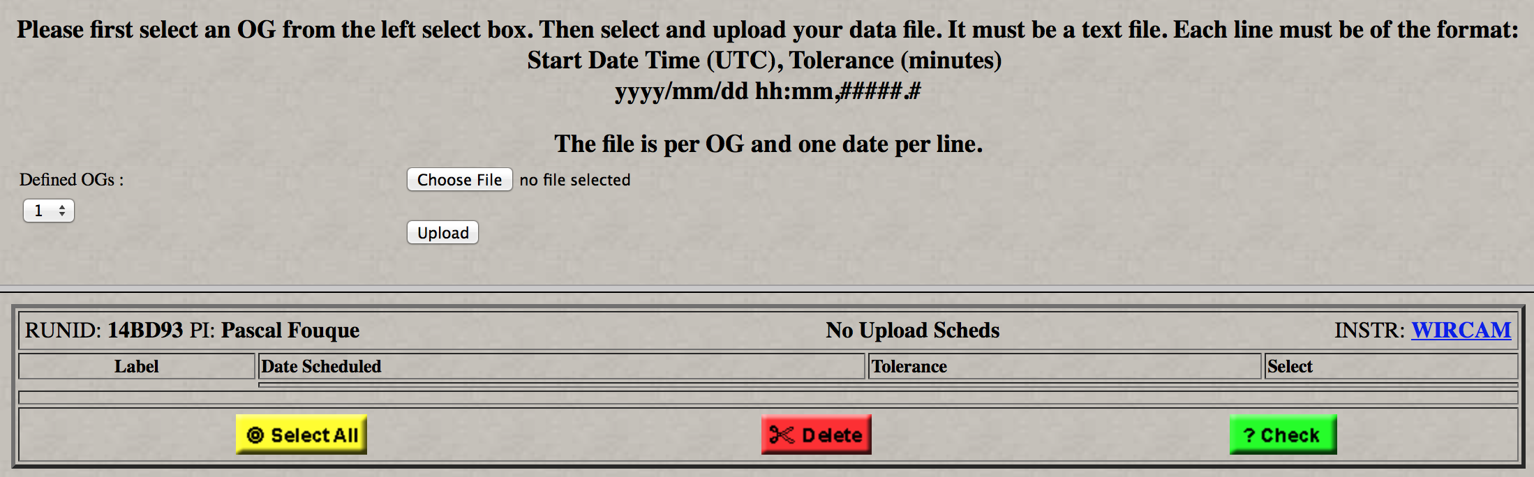
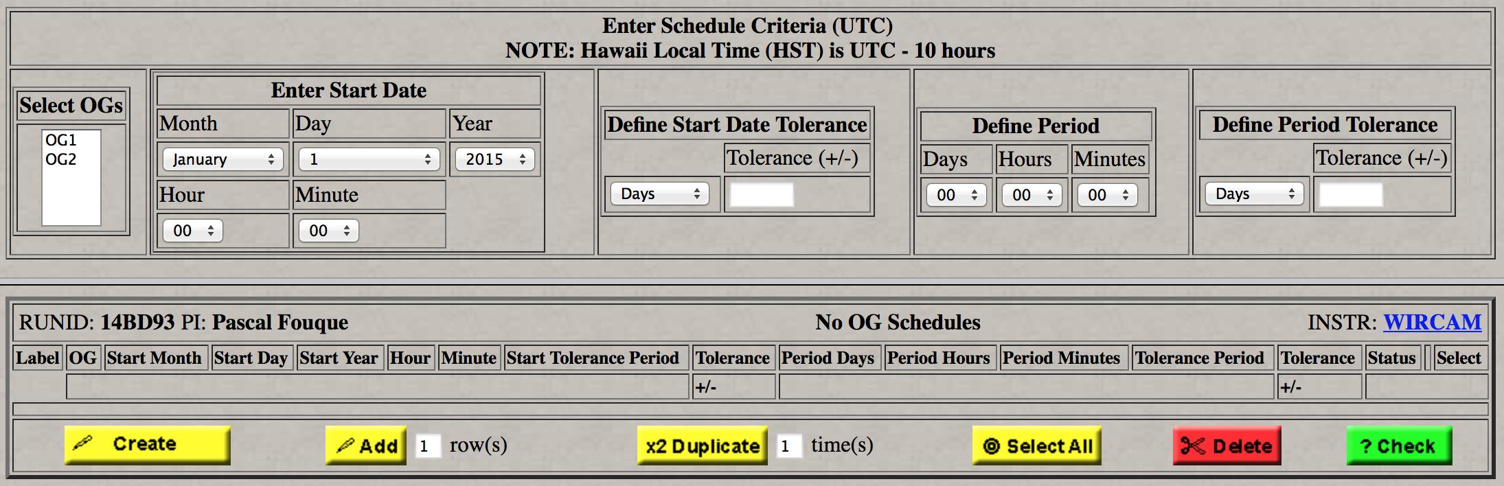
For 2015A, three options are available if time constrained observations need to be entered: (1) constraint for the start date and time of an OG, with a tolerance, (2) list of possible dates and times, with a tolerance, (3) schedule calculated from a start date and a period. See the Prg Constraint page.
There is also a new way to enter pointing offsets that ensures that the target coodinates are not changed. See the Fixed Targets section for additional details. A Moon distance and tolerance have been added in the Constraints section.
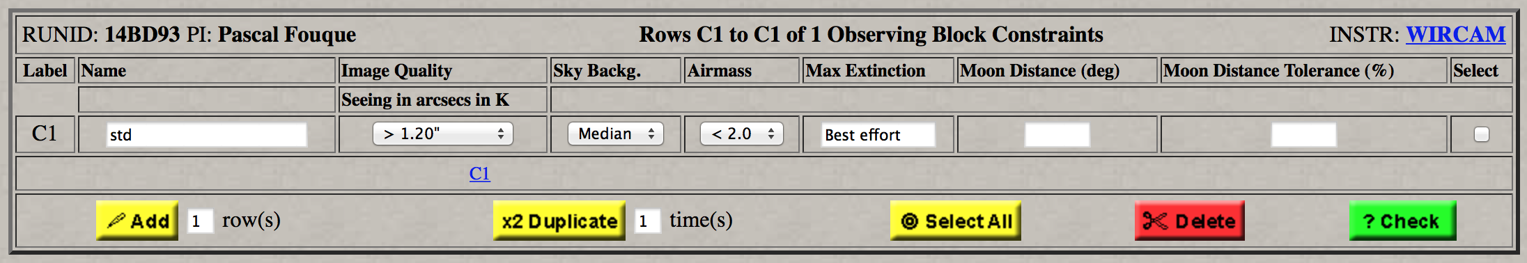
Starting with 2011B, there is one additional optional piece of information that PIs can provide: maximum extinction (in magnitudes).
On the Constraints page, there is a field "Max Extinction". By default, the value is "Best effort", which means that the QSO Team will observe with the best sky conditions possible, but might observe with a bit of extinction too, if it is judged that the science will not be affected. The value can be changed by the user.
For WIRCam, the Remote Observer will use the value of extinction as measured on the mosaic itself.
If the actual extinction is within the indicated limit +/- 0.02mag, the grade will be 1 or 2 (depending on extinction and other parameters), the exposure will be validated and charged to the PI, and we will do repeats of that exposure to compensate of the loss of flux, unless the PI indicates (in the PH2 comments box) that repeats are not necessary.
If the actual extinction is above the indicated limit +/- 0.02mag, the grade will be 3 or higher and the exposure will not be validated (and not charge ot the PI); the exposure will be tried again at a later time.
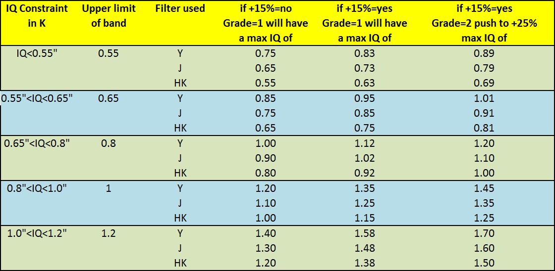
A new table provides details about IQ as a function of filter, and QSO grades as a function of IQ measured. The section Constraints explains the details summarized in the table.
WIRCam is not a very efficient instrument in terms of telescope time use. This is mainly due to short exposure times, limited by the high sky background in the near-infrared. For bright objects, any individual exposure time of, for instance 5sec, will be followed by a readout time of 2x2.4=4.8sec (there are in fact two readouts for the REF and RAW images).
In addition, an Observing Group observation is generally started by an Acquire image, to get a good astrometry and initialize the guiding process. Finally, dithering patterns are used to subtract the sky background. Each dithering implies a telescope offset and a guiding initialization, which add overheads.
Here we report an estimate of these overheads, so that users can evaluate the efficiency of the observing strategy that they plan to use.
In conclusion, the WDP mode is very inefficient at the telescope and should be used only when absolutely necessary (large objects). See more details about WDP in the Instrument Configuration section.
The User ID and Password are sent to new users by the QSO Team, by email. If you have used PH2 before but not remember your information, please contact the QSO Team.
The navigation buttons and their corresponding pages are described below.
| First page of PH2 (Login). User ID and Password required. | |
| Program Selection Page, for multiple programs under the same User ID | |
| Page describing the QSO program, the investigators (PI) and the TAC evaluation. | |
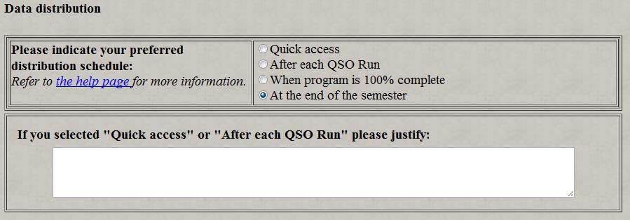
| General Constraints and Information for the program. Depending on the answers, some options will be made available in the subsequent pages. Please use the box provided to add as many instructions as possible (priorities, acceptable extinction, if IQ can be pushed, exact requirement for photometric conditions, Moon distance or illumination constraints, etc.) Includes a section for the distribution of the data. | |
| Page containing the table used to define all of the fixed targets used in the creation of the observation blocks | |
|
Page containing the table used to define all of the targets for which coordinates are changing with time (ephemeris). Only accessible if requested in Program Constraints page |
|
|
Page allowing to upload Finding Charts |
|
|
Page used to define user dithering patterns. Only use if absolutely necessary, otherwise use provided DPs. Not mandatory and only accessible from the navigation menu |
|
| Special form used to define nodding
(target-sky-target...) patterns for WIRCam. Not mandatory and only
accessible from the navigation menu, if user specifies so in the Prg
Constraints page. |
|
| Special tool used to indicate regions to avoid
using for guiding purposes for WIRCam. Not mandatory and only
accessible from the navigation menu, if user specifies so in
the Prg Constraints page. |
|
| Page containing the table used to define all of the instrument configuration (e.g. filters, exposure time, dithering pattern) used in the creation of the observation blocks | |
| Page containing the table used to define all of the sky constraints entering in the creation of the observation blocks. | |
| Page allowing the creation of the observation blocks from the lists of targets, instrumental configurations and constraints defined in the previous pages. | |
| Page allowing the creation of the observation groups (e.g. sequences) from a list of observation blocks. The I-time used for the program is also calculated and compared to the time allocated by TAC. Time constraints and REEL can be accessed here, if requested. | |
| Page allowing to upload a list of date constraints to schedule OGs. This page only appears if the corresponding option has been activated in the Prg Constraints menu | |
| Page allowing to specify a start date and period to schedule OGs. This page only appears if the corresponding option has been activated in the Prg Constraints menu | |
| Page describing all the observations prepared with PH2 and stored in the database for a specific program. | |
| Logging out of PH2 (needs confirmation). | |
| Opens the quick help files for PH2, containing information on the diverse parameters of the PH2 forms. | |
| This document! Detailed overview and general description of PH2 and how to use it. |

This page can be opened at all time; it is possible to work on several programs at the same time without having to log out from PH2. The programs are first sorted out according to the semester (pull-down menu) and then are identified by the runID, instrument, and title. Be careful: always make sure that you are editing the right program! For your convenience, the runID is shown on all the PH2 forms. Note: Following recommendations by the Time Allocation Committee, it is possible that a program was split into different programs with some specific I-time and grade/rank. If it's the case, the program with the higher ranking will keep the same runID as assigned during Phase 1 but the other programs will be assigned a different runID by the QSO Team. You must first select a program and click on the "Proceed" button before being able to navigate through the other pages of PH2.
| |
|
| Open the help files to the current page. | |
| Save the content of the current page in the QSO database and open the next form. |

| |
|
| Open the quick help files to the current page. | |
| Cancel all the modifications done to the current page and reload data stored in the database. | |
| Save all the modifications done to the current page in the database and reload current page. | |
| Save the content of the current page in the QSO database and open the next form. |
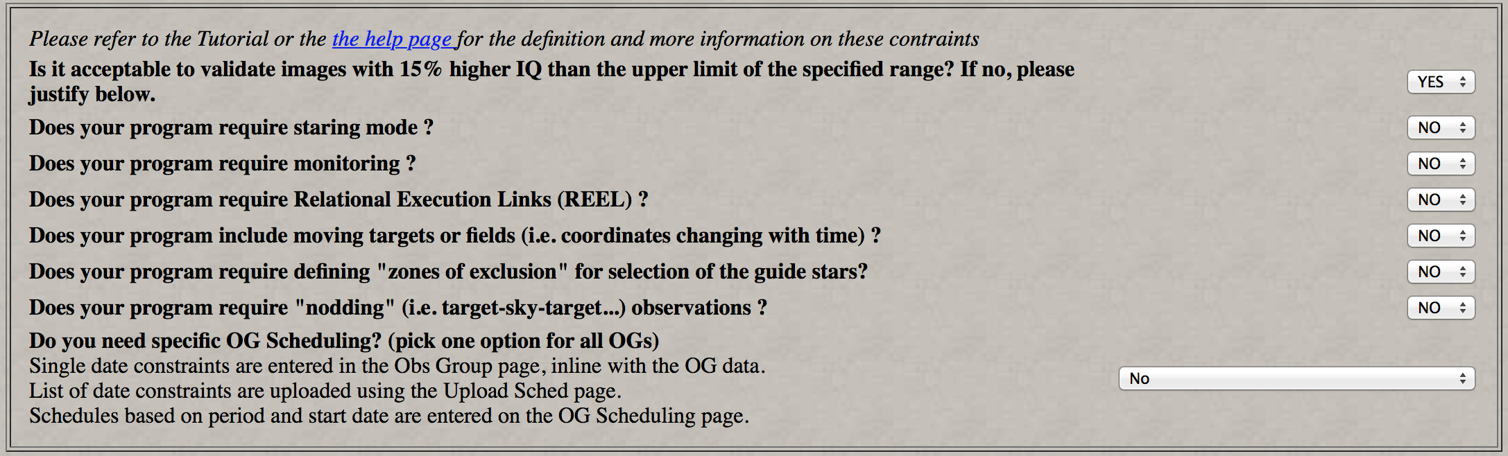
This page requests some important information regarding your QSO program. Depending of some of the answers you provide here, options will become available in the subsequent pages of PH2. This page is divided into several sections:
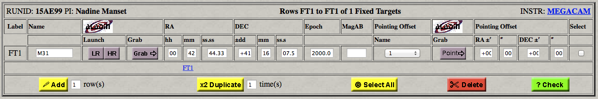
This is the first step toward the creation of the observation blocks, and where the user defines the fixed targets of the program and their precise pointing coordinates. The target table includes the target name, coordinates, and a pointing offset. A few buttons allow the addition, duplication, selection or deletion of entries. The maximum number of rows displayed at once is five. The "Next Page" and "Previous Page" buttons can be used to navigate between the different pages. The blue hyperlinks FT# represent the first row of each individual pages and can also be used for moving quickly from a page to another.
If you plan to use the "WIRCam Dithering Pattern" (WDP), that is put the object successively on each array of the mosaic, the pointing coordinates should be set in order to have the object at the "1" position (see below).
Pointing Offsets: The telescope pointing is adjusted such that the requested RA and Dec target position is placed in the lower right corner of chip 60, at an offset of +52,-52 arcseconds from the center of the mosaic. All offsets are applied relative to this position, not to the mosaic center. The 5 positions are predefined offsets, illustrated below. These offsets are useful if you want to put the target at a specific location on the mosaic. By selecting the "New" button, you can edit the offset fields and define new positions. When the page is saved, these offsets are refereed under the name U_nnn (U for "user") and this option becomes available for all the targets in the table. After the save, it is not possible to redefine the values for a given customized offset. Just create a new one... When the target coordinates are rather entered with Aladin, the pointing offsets are set to zero. NOTE: As shown, the default offset "1" does NOT correspond to the physical center of the mosaic (center of the cross) but is rather shifted by 52 arcseconds from it to ensure that the object falls on a chip.
The "LR" and "HR" buttons are used to display a field with either a "Low Resolution" (field of view of 1.5 x 1.5 degrees; 1 pixel = 6.8"), or a "High Resolution" (15 x 15 arcmin image; 1 pixel = 1.7"). The HR image can be used for accurate positioning, but due to the display limitations and the astrometry of the plates, the pointing accuracy of Aladin will never be better than 3-4". Aladin works only with coordinates for J2000.0. The coordinates sent back are automatically in J2000.0. Please also note that the slight rotation of the superimposed WIRCam grid does not mean that we can rotate the mosaic!
As an example, the low resolution field surrounding M27 in the Aladin window will look like:

An image of the target is displayed, stars in the fields are identified from the GSC with red circles, and a grid showing the WIRCam mosaic (including the gaps) is superimposed (see below for correct identification and orientation of the arrays). The coordinates indicated at the top left refer to the position of the center of the mosaic, indicated by the red cross, at the bottom corner of array 60. By clicking and holding the left button of the mouse, the mosaic can be moved across the field to position exactly the object where it should be. To be very precise, the zooming option can be used. When the object is correctly positioned, the pointing coordinates (that is, the center of the mosaic showed as the red cross) can be transferred to PH2 by simply clicking on the "Grab" button in the PH2 table, before closing the Aladin window. The coordinates will be included in the table and the pointing offsets set to zero; the target coordinates have now been transformed into pointing coordinates.
As shown in Aladin, the WIRCam mosaic has two different series of gaps between the detectors:
Very bright stars will saturate the chips so if it is an issue for your fields, you can use the GSC stars displayed in Aladin (magnitude is given by clicking on the red circles) and the moving grid to carefully define the target pointing.
These functionalities of grabbing the pointing are useful when one wants to adjust the field-of-view, so that for instance a bright star does not fall on the mosaic. It is recommended to use the "Point" button, as this keeps the initial coordinates of the target and adjusts the offset accordingly, allowing a check of the field in case of doubt. If you modify the coordinates target, we cannot know if an apparently bad centering is intentional or not.
In the Aladin window generated after using the Aladin "LR" or "HR" button (to the left), click on the crosshair and hold to move the outline of the mosaic with respect to the field of interest. Once the outline of the mosaic has been re-positioned, click again on the default position (where the 4 small green squares are) to modify the target position (do not click on the target: the crosshair marks the telescope position). The "Point" button will figure out the appropriate offsets, and enter those values in the pointing offset boxes. This functionality cannot be used for staring mode programs.
The following is a template of the Astrores file that you can copy to your local machine to use the download/upload features:
<?xml version = "1.0"?>
<!DOCTYPE ASTRO SYSTEM "http://vizier.u-strasbg.fr/xml/astrores.dtd">
<ASTRO ID="v0.8" xmlns:ASTRO="http://vizier.u-strasbg.fr/doc/astrores.htx">
<TABLE ID="Table">
<NAME>Fixed Targets</NAME>
<TITLE>Fixed Targets for CFHT QSO</TITLE>
<!-- Definition of each field -->
<FIELD name="NAME" datatype="A" width="20">
<DESCRIPTION>Name of target</DESCRIPTION>
</FIELD>
<FIELD name="RA"    datatype="A" width="11" unit="h" format="RAh:RAm:RAs">
<DESCRIPTION>Right ascension of target</DESCRIPTION>
</FIELD>
<FIELD name="DEC"   datatype="A" width="11" unit="deg" format="DEd:DEm:DEs">
<DESCRIPTION>Declination of target</DESCRIPTION>
</FIELD>
<FIELD name="EPOCH" datatype="F" width="6">
<DESCRIPTION>Epoch of coordinates</DESCRIPTION>
</FIELD>
<FIELD name="POINT" datatype="A" width="5">
<DESCRIPTION>Pointing name</DESCRIPTION>
</FIELD>
<!-- Data table --><DATA><CSV headlines="4" colsep="|">
<![CDATA[
NAME                |RA         |DEC        |EPOCH |POINT|
                    |hh:mm:ss.ss|+dd:mm:ss.s|      |     |
12345678901234567890|12345678901|12345678901|123456|12345|
--------------------|-----------|-----------|------|-----|
M33                 |01:33:51.02|+30:39:36.7|2000.0|1    |
NGC4258             |12:18:57.54|+47:18:14.3|2000.0|1    |
NGC3359             |10:46:36.30|+63:13:29.0|2000.0|1    |
NGC2903             |09:32:11.67|+21:37:21.6|2000.0|1    |
]]></CSV></DATA>
</TABLE>
</ASTRO>
To upload a file, you can first save the example on your local machine by clicking on the "Astrores" button. All you have to do is to copy this template to your local machine within your favorite editor and then edit the ASCII table with your targets (do not change the XML code!). It is crucial that you keep the appropriate format. Use the vertical lines as references for the number of spaces allowed. Most editors will keep this format automatically so it should not be a problem.
Important: Versions 6 and 7 of Netscape have an unfortunate bug affecting the translation of the XML template downloaded and ruins the format of the file. There is a workaround: 1 - After opening the Astrores template, go to "view page source" in the top menu. This will shows the HTML code. 2 - With the mouse, copy all the code between the" XMP and /XMP lines and paste to an editor. 3 - Edit the two occurrences of lowercase "table" appearing in the code to uppercase "TABLE", and save. The file is now ready to be edited and is uploadable. You can upload the file to PH2 by giving the right path and by clicking on the "Upload" button. We strongly encourage you to verify carefully your target list after that!
| Button | Function |
| Add N rows to the table. | |
| Duplicate the selected rows N times. | |
| Select all the rows in the table. Clicking again on it deselect all the rows. | |
| Delete the selected rows. A confirmation window is displayed. | |
| Check the entries for errors. The errors found are displayed in a separate window and are indicated by a red frame in the table. An automatic check is done also when the form is saved or when the "proceed" button is activated. | |
| Display the next rows of the table. | |
| Display the previous rows of the table. | |
| Cancel all the modifications done to the current page and reload data stored in the database. | |
| Save all the modifications done to the current page in the database and reload current page. Regular saving of the current form is recommended! | |
| Save the content of the current page in the QSO database and open the next form. |
This form is used to define targets for which coordinates change with time. The form is only accessible if requested in the Program Constraints section.
The general idea behind the ephemeris form is very simple: define a series of coordinates for a specific time for a given target. The top of the form, illustrated below, allows the user to first give a name to a target:
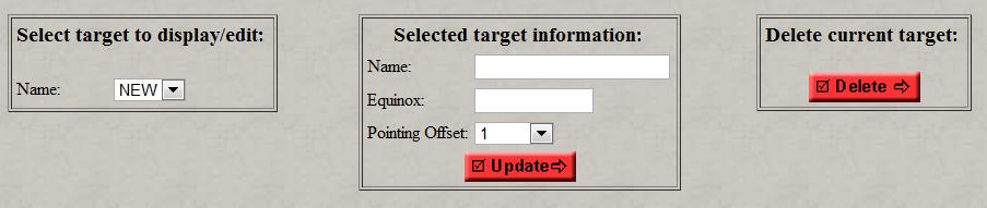
For instance, in the pull-down menu on the left, you can select "New". In the central window, you can then give a name to your target. "Pointing Offset" refer to options for pointing offsets explained in the above "fixed targets" section. When you click on "Update", the table in the middle frame window is then created and your target receives a label "ET#" (for "ephemeris target").
The table below shows the entry fields for the ephemeris of the target specified:

Each row in the table is an ephemeris labeled "E#" and includes the UTC Date (beginning of a night in Hawaii is ~ 05:00:00 UT) and the coordinates of the target for this date (in J2000.0). As many ephemeris as wanted can be entered for a target and as many targets as wanted can be entered for a program. After defining all of the ephemeris for the target, we recommend that you save it immediately before starting defining the ephemeris for the next target (if needed). When saved, the ET will appeared in the list of targets used for defining the observation blocks (below).
Since entering a large number of ephemeris can be cumbersome the Astrores format template can be used at the bottom of the page to upload ephemeris for a given target (that is, one upload per target is necessary). To do so, apply first the procedure described above (create a new target name and click on update), since the name of the target cannot be defined from the Astrores template. Below there is a Astrores template (XML) that can copied on your local machine and then used to upload ephemeris to the table in the middle frame. (You can also create your own template on your local machine by first defining a target and click on "download". However, see important note in the fixed target section if you are using Netscape 6 and 7). It is important that the format is respected. You can then prepare the ephemeris for the target as seen in the lower part of the template and save the template under a specific name. When saved on your local machine, you can then upload it by specifying the path. Check that everything is fine and then save the ephemeris table for that target. Repeat if necessary!
<?xml version = "1.0"?>
<!DOCTYPE ASTRO SYSTEM "http://vizier.u-strasbg.fr/xml/astrores.dtd">
<ASTRO ID="v0.8" xmlns:ASTRO="http://vizier.u-strasbg.fr/doc/astrores.htx">
<TABLE ID="Table">
<NAME>Ephemeris</NAME>
<title>Ephemeris for CFHT QSO</title>
<!-- Definition of each field -->
<FIELD name="DATE_UTC" datatype="A" width="19" format="YYYY-MM-DD hh:mm:ss">
<DESCRIPTION>UTC Date</DESCRIPTION>
</FIELD>
<FIELD name="RA_J2000" datatype="A" width="11" unit="h" format="RAh:RAm:RAs">
<DESCRIPTION>Right ascension of target</DESCRIPTION>
</FIELD>
<FIELD name="DEC_J2000" datatype="A" width="11" unit="deg" format="DEd:DEm:DEs">
<DESCRIPTION>Declination of target</DESCRIPTION>
</FIELD>
<!-- Data table -->
<DATA><CSV headlines="4" colsep="|">
<![CDATA[
DATE_UTC           |RA_J2000   |DEC_J2000  |
YYYY-MM-DD hh:mm:ss|hh:mm:ss.ss|+dd:mm:ss.s|
1234567890123456789|12345678901|12345678901|
-------------------|-----------|-----------|
2003-06-04 06:30:00|09:34:00.00|+16:38:00.0|
2003-06-05 06:30:00|09:35:15.00|+16:31:50.0|
2003-06-06 06:30:00|09:36:33.00|+16:25:40.0|
]]></CSV></DATA>
</TABLE>
</ASTRO>
This form allows the user to define his/her own dithering patterns. It is NOT a mandatory form and is only accessible from the navigation menu (i.e. "Proceed" from the "Fixed Targets" form will go to the "Instrument Configurations" form, not this one. Defining his own dithering patterns can be useful for some programs.
Our experience, however, shows that data reduction can become much more difficult or can even be severely compromised with nonstandard patterns. Also note that for good sky subtraction, a dither pattern with a minimum of four positions is needed; for fewer dither positions, the pipeline is designed to return only a detrended image with no sky subtraction performed, and thus avoid degrading the data quality with a poorly constructed sky image. Despite this, should the PI choose DP3 or lower (for a specific science case), the PI must also assume the responsibility of carrying out the sky subtraction. Creating non-standard dither patterns therefore requires previous extensive experience with infrared data reduction of wide-field camera observations. For any doubt, please do not hesitate to contact the QSO/I'iwi Teams.
The idea behind this form is simple: the user can define a list of absolute offsets and saved this list as a dithering pattern under a customized name. This name can then be found under the pull-down menu for the available dithering patterns in the next PH2 form ("Instrument Configurations").
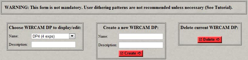
The top frame allows the user to visualize the offsets of a dithering pattern, create a new pattern, or delete a user pattern.
The middle frame displays the table used to define the dithering pattern:
Here is table with the list of the available buttons:
| Button | Function |
| Add N rows to the table. | |
| Duplicate the selected rows N times. | |
| Delete the selected rows. A confirmation window is displayed. | |
| Select all the rows in the table. Clicking again on it deselect all the rows. | |
| |
Check the entries for errors. The errors found are displayed in a separate window and are indicated by a red frame in the table. An automatic check is done also when the form is saved or when the "proceed" button is activated. |
| |
Display the next rows of the table. |
| |
Display the previous rows of the table. |
| |
Cancel all the modifications done to the current page and reload data stored in the database. |
| |
Save all the modifications done to the current page in the database and reload current page. Regular saving of the current form is recommended! |
| |
Save the content of the current page in the QSO database and open the next form. |
Infra-red astronomy differs from visible observations mostly because the sky background is a strong contributor and is much more variable. The near-IR sky on Mauna Kea can change by up to 10-20% in a few minutes. This is why exposure times and observing strategy must be able to frequently sample the sky. If the object is not very extended, the sky cn be derived in regions of the mosaic without scientific signal for each dithering pattern position. However, when the object is extended (e.g. > 40% of the field of view of the mosaic), another technique must be used to sample the sky: nodding. The idea is simple: during the observations on the target, the telescope is slewed to a position away from the object in order to frequently established the sky background. For WIRCam, this is possible by applying regular offsets to the telescope.
PH2 offers a special (optional) form to define nodding patterns. The idea behind the form is this: define a precise sequence of observations (i.e. target-sky-target...) in order to be able to adequately sample the sky on a position close to the object and defined by offsets with respect to this target. The form in PH2 will appear quite complex at first but is in fact simple to use and allows the user to quickly define complex sequences. At the touch of a few buttons, the form allow the user to:
There are two important things to take into account before defining the patterns:
The top frame is where the user can fully define the nodding pattern for a given target:
The yellow frame display the WIRCam mosaic at the location of the sky region as defined by the offsets with respect to the target. By selecting the frame with the mouse, it's possible to move it and fine-tuned the location. When this is done, the "grab" button in the top frame form of the nodding form can be used to update this new position for the sky.
When the "create" button is selected, the table of offsets is displayed in the middle frame. All of the entry fields remained editable and additional offsets can even be added. The type of observation (target or sky) is described as well as the type of offset (e.g. target -> sky). When the user is satisfied, clicking on "save" will save the pattern and make it available in the Instrument Configuration form for further creation of the observation blocks. There is no simple way to directly edit an existing nodding pattern yet. The way to do it is like this: 1) View the existing pattern; 2) Change the name of the pattern in the create window; 3) Edit the pattern as needed; 4) Save.
Example
Nodding observation of an extended target is required from a user following this strategy: five exposures on the target with a sky region located -1.5 degrees away in RA sampled every target exposure. For each exposure, micro-dithering is requested (1 loop of 4 micro-exposures; see instrument configurations). The nodding starts on the target and the DP is also applied on the sky. After selecting the appropriate entry fields in the form and saving the offsets, the observing sequence resulting in this strategy is illustrated in the figure below:
In this example, the sequence of offsets will be T1-S1-T2-S2-T3-S3-T4-S4-T5-S5, which each DP position producing a data cube of 4 exposures generated by the optional micro-dithering mode (instrument configuration).
Guiding for WIRCam is done on the arrays themselves, with one guide star chosen on each array to provide stable guiding. Acquisition software selects the guide stars according to their magnitude and location. Normally, the limiting magnitude for guide star selection is Ks ≤ 14mag; only stars well away from chip edges (> 100'') and clear of cosmetically poor regions ( bad pixels ) are selected. Note that your primary science target, even if it is a bright star, is never chosen for guiding, if you use the pre-defined offsets . Small guiding windows (size ~5" x 5") are then automatically positioned on those stars for guiding. Since those windows are read at a high rate, stars selected for guiding cannot be used for scientific purpose. For most scientific programs, this will not be an issue. However, for programs looking at bright stars, guiding might result in the lost of science if one of the interesting targets is choose for guiding.
To avoid this problem, we have developed a simple tool in PH2 with which the user can define small 30" x 30" exclusion zones for guide star selection. This information is passed to the acquisition software during the observations and the algorithm for guiding selection automatically rejects stars located in those exclusion boxes. The form needed for that in Ph2 is optional and is only available when requested in the program constraints page.
Important Note 1: Use the exclusion zone tool only if you need it, that is, if you plan to use one or more of the bright stars (other than the primary target) in the chosen WIRCam field of view for science purposes (eg., for performing differential photometry). Since guiding priorities are established according to the magnitude of the object, it might be preferable to use the Exclusion Zones tool to make sure that you will not lose important comparison stars. Usually, programs targeting extragalactic sources (galaxies) do not need to define exclusion zones.
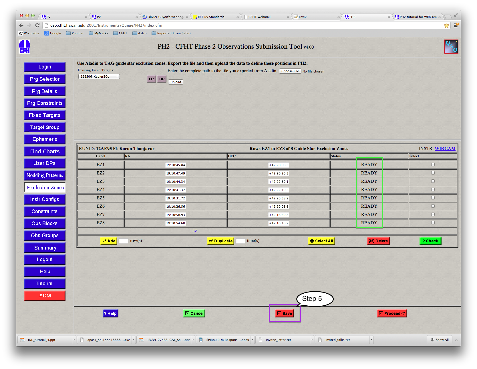
Important Note 2: Exclusion zones are directly linked to the target positions as defined in the fixed target (FT) form. Before you define exclusion zones, make sure that the target coordinates are properly defined. If the target coordinates are changed after the corresponding exclusion zones have been defined, all these zones will be invalidated and you have to start all over again!
Important Note 3: Exclusion zones are only possible for fixed targets. Targets defined by ephemeris positions cannot be used for defining zones of exclusion.
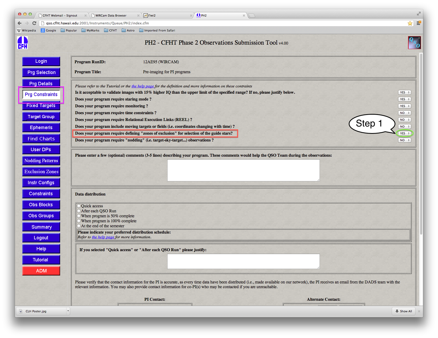
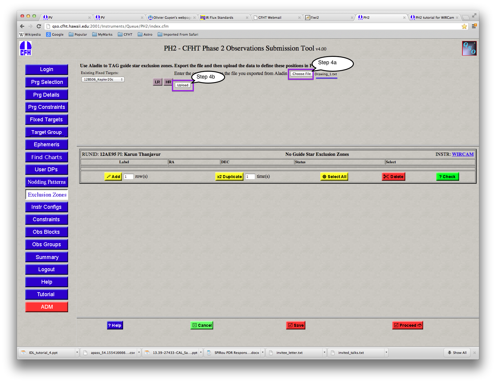
Since Exclusion Zones are only used for special scientific purposes, its use must be first specifically defined in Ph2. This is done in the program constraints ("Prg Constraints") form by setting the exclusion zones query to "Yes", as shown in the screen shot above (the default value is "No").
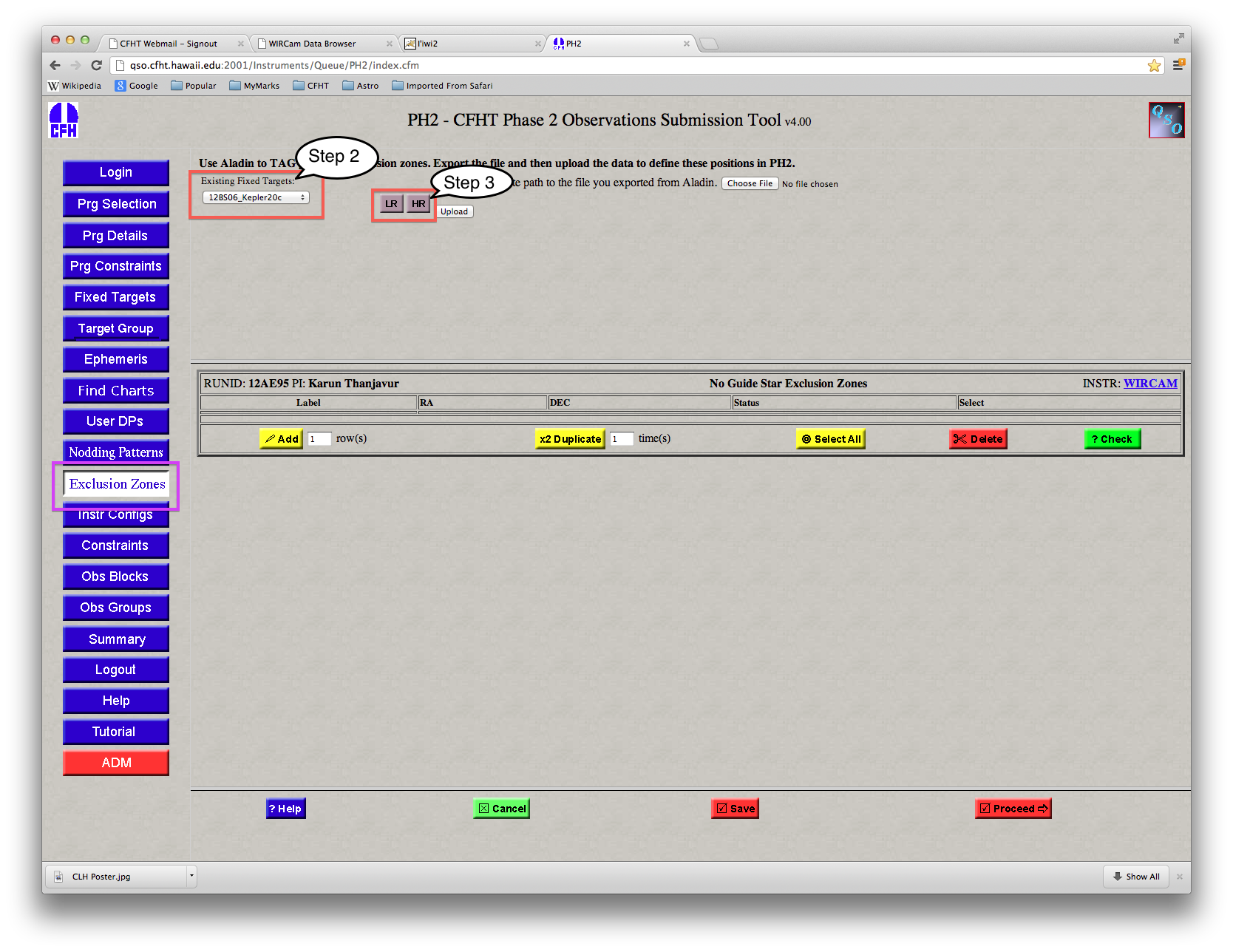
Next, in the Ph2 "Exclusion Zones" form, select the target for which you are defining the exclusion zones by using the 'Existing Fixed Targets' button (as shown in the figure); on clicking the button, all the FTs defined in this program will be displayed, and you have to pick the appropriate FT. After picking the FT, bring up the Aladin window in either the low resolution (LR) or high resolution (HR) mode; for exclusion zone definitions, the HR is preferred so that the stars may displayed properly and picked, especially in crowded fields.
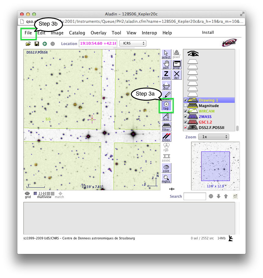
Aladin displays the field of the fixed target selected, and also automatically overlays the WIRCam field of view (showing the four chips), the Guide Star Catalog (GSC) and the 2Mass catalog, as shown in the screen image. Here, the target is displayed in the high-resolution mode; the field of view may be changed using the zoom and pan buttons.
Select the "Tag" button, then choose each of the exclusion zone stars using the mouse (left button). As each star is chosen, Aladin displays a yellow plus symbol; Aladin also displays a panel titled 'Drawing 1' as seen in the screen image.
Once all the exclusion zone stars have been selected, their cooridnates have to be
exported to a data file (in ASCII format). This is done in Aladin, under "File",
then "Export Planes" (as shown in the screen image below) which brings up a
filename dialog box. Enter the appropriate directory but leave the filename
unchanged (make sure 'Drawing 1' is selected as shown in the screen image)

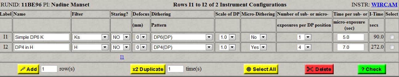
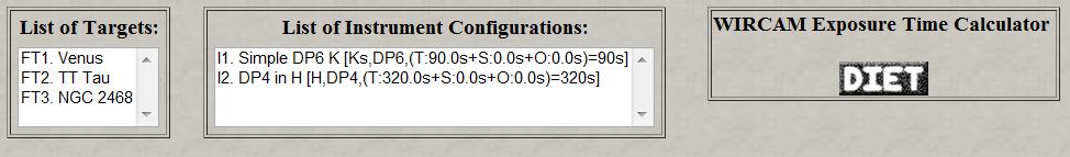
This is the second mandatory step in the creation of the observing blocks, used to define all the instrumental configurations necessary for the program. The same configuration can be used several times with different targets. The main section of the page is a table with different options under pull-down menus or editable entry fields.
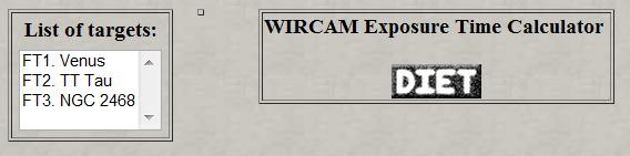
The top frame can be used to help in the preparation of these configurations by offering the following elements:
The middle frame of the configuration page consists in a table and buttons to manipulate the entry fields:
Basic Dithering Patterns
The WIRCam mosaic has only one series of gaps between the detectors which have all the same size (45"). The pre-defined basic dithering patterns offered for WIRCam (DP#) at this time cover those gaps and the bad pixel regions on the mosaic. The DP offsets are detailed in the following tables. The "DP" patterns can be used with two scale factor. Scale 1 covers the bad pixels regions and mosaic gaps. Scale 1.5 will cover all of those plus give a better sampling of the sky.
The following tables display the various offered offset patterns in arcmin: DP2-DP4, DP5-DP21 and WDP1-WDP5
WIRCam Dithering Patterns
The pre-defined WIRCam dithering patterns (WDPs) are special patterns which put an object on the center of the four arrays. The number following WDP indicate the number of loops; a limit of 5 loops, that is 20 cubes, is possible. Offsets are automatically applied each time the object comes back to a specific array to help removing bad pixels and sky background. The figure below illustrates the 20 cube that a WDP5 would do. Note of course that each cube can have several sub- or micro-exposures.
IMPORTANT NOTE: If you plan to use WDPs, make sure that the pre-defined pointing offsets in the fixed targets table is set to 1, so that the reference position is at the bottom right corner of chip 60. This will ensure that position #1 puts the object at the center of chip #60, and that the following positions center it in chip #54, #52, and #77 successively.
For wide dither patterns when at a declination of greater than 40 degrees an acquire must be performed at every position. Unfortunately, at this area of the sky the pointing accuracy of the telescope on a 10 arc minute offset is not accurate enough to ensure that the guide star will fall within the 16x16 guide star box on the detector. As a result, an acquire must be performed for each dither position to determine where the stars are following each offset. On other wide dither patterns (< 40 degrees in dec) you will experience two acquires taken during the dither pattern. A second acquire is necessary to ensure that a pool of detected stars matched with the catalog is obtained such that at least two guide stars can be used for every pointing position within the dither pattern (Tom Vermeulen).
Micro-dithering: The pixel scale in WIRCam is 0.3"/pixel so the best image quality which is adequately sampled is ~0.7". To make good use of better seeing, WIRCam uses micro-dithering: 4 individual exposures, shifted by 0.15" on a square grid, provide Nyquist sampling of the recombined image for all conditions (several groups (up to 7) of 4 micro-dithered exposures can be done sequentially on one dithering pattern position (a cube)). In some cases this may require additional detectors readouts, and therefore introduce overheads. Note that micro-dithering is not expected to yield much improvement when the natural seeing is ~ > 0.8". For the YJHKs filter set, the user has the choice of using micro-dithering or not in this column. Since micro-dithering requires good (bright) guide stars, it is not offered for narrow-band filters. The next column options is defined by this selection. The micro-dithering mode requires guiding as it uses the guiding stars to control the offset produced by the ISU. This requirement is checked in the observing block PH2 form.
Number of sub- or micro-exposures: Number of sub-exposures or micro-exposures (N) per exposure of the DP (that is, the number of exposures within the cube). To keep the size of the files manageable, N < 12. Of course, for micro-dithering exposures, N = 4,8,12.
Exposure Time: Exposure times for the individual sub- or micro-exposures taken within the dithering pattern. As of 2008B, the lower limit is 2.5 seconds. For WIRCam, the upper limit depends on the filter selected to avoid saturation by the sky background. The current maximum exposure times for each filter are given in the following table:
| Filter | Maximum Exptime |
| Y | 150 seconds |
| J | 60 seconds |
| H | 15 seconds |
| Ks | 25 seconds |
| LowOH-1, Low OH-2 | 3000 seconds |
| Ch4-On, CH4-Off | 50 seconds |
| H2(1-0) | 200 seconds |
| Kcont | 200 seconds |
| Br-gamma | 200 seconds |
Integration Time Calculation
The integration time (I-time) calculation is done for each instrument configuration (IC) according to the general formula:
I-time
(IC) = I-time (target) + I-time (Sky) + Overheads (target + sky)
where
I-time (target) = [Number of DP exposures x number of sub- (micro)
exposures x Exptime] on target
I-time Sky) = [Number of DP exposures x number of sub- (micro)
exposures x Exptime] on sky region
Overheads (target + sky) = readout 10sec overhead (target + sky) per
sub- or micro-exposure + 60 sec x Number of Offsets for nodding
Of course, if no nodding is used, no I-time or overheads are charged for the sky exposures and offsets. At the moment, readout overhead = 10 seconds. The actual readout of the camera is shorter but there is all kind of other overheads related to the operations of WIRCam to achieve an exposure that must be taken into account. In short, each sub- or micro-exposure has an total overhead of 10 seconds.
The following table shows the available buttons:
| Button | Function | |
| Add N rows to the table. | ||
| Duplicate the selected rows N times. | ||
| Delete the selected rows. A confirmation window is displayed. | ||
| Select all the rows in the table. Clicking again on it deselect all the rows. | ||
| Check the entries for errors. The errors found are displayed in a separate window and are indicated by a red frame in the table. An automatic check is done also when the form is saved or when the "proceed" button is activated. | ||
| Display the next rows of the table. | ||
| Display the previous rows of the table. | ||
| Cancel all the modifications done to the current page and reload data stored in the database. | ||
| Save all the modifications done to the current page in the database and reload current page. Regular saving of the current form is recommended! | ||
| Save the content of the current page in the QSO database and open the next form. |
This page presents the table designed for defining the sky constraints under which the observations should be undertaken. The top frame displays information about the targets and instrument configurations defined previously:
The middle frame presents the table for the constraints:

The constraint on the band image quality is the strongest criterion for the selection of a program to be undertaken. The QSO Team will try to respect the constraint on the image quality at all time for your observations. Our goal is to never exceed the upper limit defined by your constraint by more than 15%, and at most 20%. Evidently, the image quality varies through a band to another.
The reference band for the QSO with WIRCam will be the K-band, that is that during the observations, the image quality will always be translated to this band. So, for instance, if you specify a limit of IQ of 0.80" for an observation with the Y filter, you could expect that an resulting image with about 1.0" would still be validated by the QSO Team. As explained above, the QSO Team will validate images within about 15% of the upper limit of the IQ specified in K band . If this is not acceptable, or if the limit acceptable is below the upper limit of the range, this should be described in the program constraints page.
| | |
| Image Quality in Y band | FWHM ~ + 0.1 - 0.2" larger than K band |
| Image Quality in J band | FWHM ~ + 0.1" larger than K band |
| Image Quality in H band | FWHM similar to K band |
| Image Quality in K band | Reference |
|
|
|
| IQ < 0.55" |
|
| 0.55" < IQ 0.65" |
|
| 0.65" < IQ 0.80" |
|
| 0.80" < IQ 1.0" |
|
| 1.0" < IQ 1.2" |
|
| IQ > 1.2" |
|
These tables show the following:
The information presented above is summarized in the table below.
Here is a table of all available buttons:
| |
|
| Add N rows to the table. | |
| Duplicate the selected rows N times. | |
| Delete the selected rows. A confirmation window is displayed. | |
| Select all the rows in the table. Clicking again on it deselect all the rows. | |
| Check the entries for errors. The errors found are displayed in a separate window and are indicated by a red frame in the table. An automatic check is done also when the form is saved or when the "proceed" button is activated. | |
| Display the next rows of the table. | |
| Display the previous rows of the table. | |
| Cancel all the modifications done to the current page and reload data stored in the database. | |
| Save all the modifications done to the current page in the database and reload current page. Regular saving of the current form is recommended! | |
| Save the content of the current page in the QSO database and open the next form. |
This is it! This page allows the user to link all the previously defined entities within observation blocks (OB). The main page is divided into two main frames:
The number of rows displayed at once is only a few. The "Next Page", "Previous Page" buttons can be used to navigate between the different pages. The blue links OB# represent the first row of each individual pages and can also be used for moving quickly from a page to another.
Here is a table with all the available buttons:
|
|
|
| Create an Observation Block, after selecting one target, one or several instrument configurations, and one constraint. | |
| Modify an observation block. After selecting one or several OBs in the table ("select" column in the table), the OBs will be modified according to the parameters defined by the top lists after clicking this button. Thus, it is possible to change the content of an OB without having to delete it and create it again. Important: You must make sure that the total I-time allocated for your program has not been exceeded after modifying the OG. | |
| Delete the selected rows. A confirmation window is displayed. | |
| Select all the rows in the table. Clicking again on it deselect all the rows. | |
| Check the entries for errors. The errors found are
displayed in a separate window and are indicated by a red frame in the table. An automatic check is done also when the form is saved or when the "proceed" button is activated. |
|
| Display the next rows of the table. | |
| Display the previous rows of the table. | |
| Cancel all the modifications done to the current page and reload data stored in the database. | |
| Save all the modifications done to the current page in the database and reload current page. Regular saving of the current form is recommended! | |
| Save the content of the current page in the QSO database and open the next form. |
Important Note for Staring mode : Each Observing block start triggers an acquire, which is unfortunate when trying to stay on the same pixel in Staring mode. It is therefore recommended to use an OB as long as possible (2 hours is the limit) and try to cover the observing sequence with as few OBs as possible: the last OB can always be aborted if the sequence is longer than the intended observing time, or if the airmass is too high.
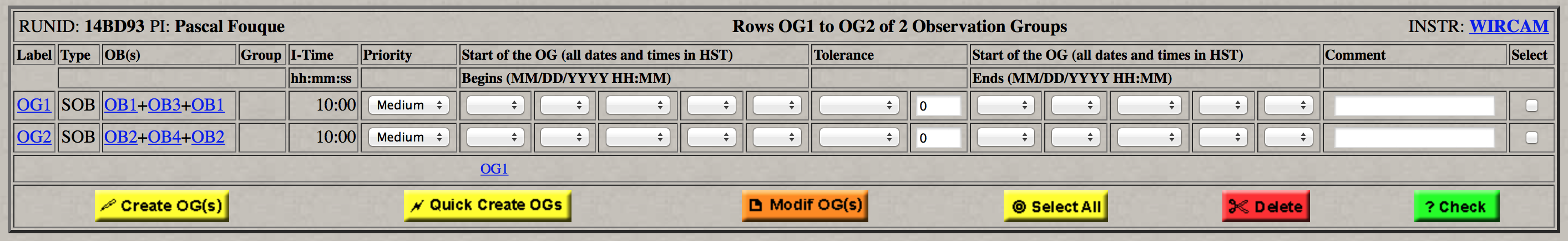
This page presents the last step in the preparation of your observations: the creation of the observation groups (OG). The OGs will be the entities scheduled at the telescope so this step is necessary, even if you have previously defined all the observation blocks. The OG page is presented below:
Observation Groups: Options
There are three important options available for the Observation Groups, useful to precise specific observations. These options are first presented in the "Program Constraints" section and appear only in the OG form if requested.
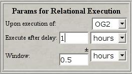
IMPORTANT: The REEL option should be used ONLY when appropriate. If the observations cannot be done within the window defined by the (delay +/- delay) (due to bad weather or technical problems), the completion of the chain will not be done. Also, the logic involved in defining the REELs in PH2 is complicated. It is preferable to define first all the OGs, save them, and then create the links. This can be done using the "modif OGs" button: after defining all the OGs, you can create the REEL link by selecting the OG from its label, entering the REEL parameters, click in the "select" box on the row, click on the "modif OGs" button and save. Deleting OGs which have REELs will not be permitted.
Here is a table of the available buttons:
|
|
|
| Create one observation group (it can be of types 1OB, MOB, or SOB). | |
| Transform all the observation blocks defined in the previous form into observation groups. The recommended approach! | |
| Modifying an existing observation group. After selecting one or several OGs in the table ("select" column), the OGs will be modified according to the parameters redefined by the top lists after clicking the "modif OG(s)" button. So, it is now possible to change an OG without having to delete it first from the table! Important: You must make sure that the total I-time allocated for your program has not been exceeded after modifying the OG(s). | |
| Select all the rows in the table. Clicking again on it deselect all the rows. | |
| Delete the selected rows. A confirmation window is displayed. | |
| Check the entries for errors. The errors found are displayed in a separate window and are indicated by a red frame in the table. An automatic check is done also when the form is saved or when the "proceed" button is activated. | |
| Display the next rows of the table. | |
| Display the previous rows of the table. | |
| Cancel all the modifications done to the current page and reload data stored in the database. | |
| Save all the modifications done to the current page in the database and reload current page. Regular saving of the current form is recommended! | |
| Save the content of the current page in the QSO database and open the next form. |
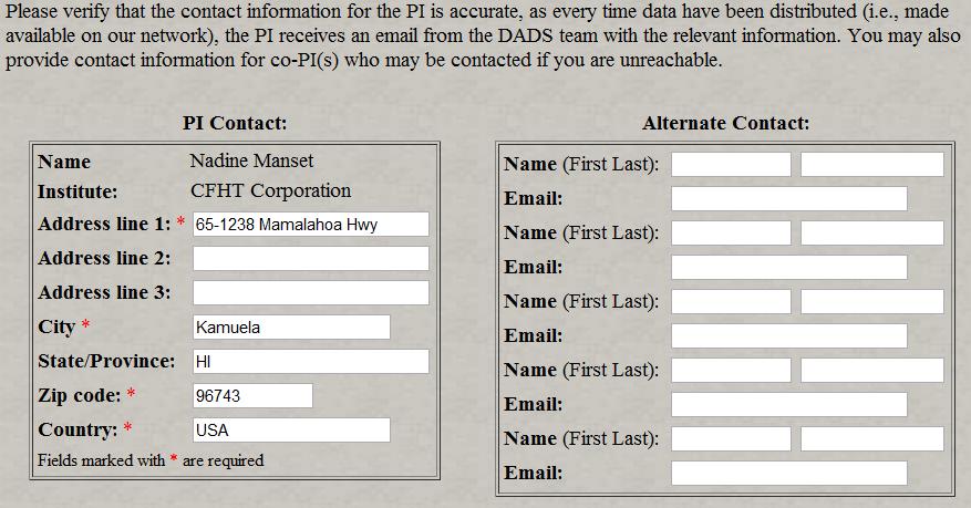
This page opens a complete summary of what is currently the Phase 2 status of the program. As showed below, the summary can be sent by e-mail to several destinations as a HTML attachment (to be compatible with people not using a browser for their mail system), by clicking on the "Send this page to" button. The summary can also be printed using the "Print" button of the browser used for PH2.

We strongly suggest that you keep the summary (printed or electronic) of the final version of the program submitted during the Phase 2. It will be useful to you for monitoring the progress of your program with the night reports and for any necessary communication between you and the QSO Team regarding the observations.
To exit PH2, you must confirm it by clicking on the "Logout" button in the window below. If you do not want to do so, select another page with the navigation buttons on the left frame.