[Contents]
[Prev]
[Next]
OSIS control and data acquisition with Pegasus
This section describes briefly the main procedures of the Pegasus
software that are used during observations with MOS. More details
can be found in the Pegasus User's
Manual
It is possible, from Waimea or Hale Pohaku, to open a Pegasus session
and to simulate observations with OSIS. Being familiar with Pegasus
procedures will significantly improve the efficiency of your first
observing nights.
Checking the status of the instrument and starting observations
When you arrive for the first night of observation, you should find
the instrument prepared in accordance with the requests you have sent
several weeks in advance of your run to CFHT. This
means that the requested detector, filters and grisms have been
installed, the internal focus has been checked for each filter, and
the direction of dispersion for each grism has been precisely aligned
with the columns of the CCD. You will find a "set-up form"
summarizing this information close to the control terminal.
Also, an image of a grid mask has been taken and processed during the
afternoon for the computation of orientation and distortion
corrections. For precise cutting of masks and for a good match
between the positions of the slits and of the objects, this step is
essential. If, under exceptional circumstances, the set-up team asks
for a few more minutes at the beginning of the night for checking
this point, it is wise to accord them this extra time.
To start a Pegasus session, type osis after the
login prompt and then type the current password (ask the OA or your
support astronomer if you do not know it). The login process creates
the appropriate icons and windows, including a top menubar: this is
the Pegasus session manager. The different Pegasus procedures are
activated by clicking on the corresponding buttons.
FIGURE 10. The OSIS session menubar

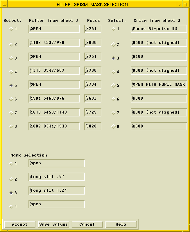
OSIS control is provided through the SIS window. To open it, click
the OSIS button on the Pegasus menubar. The window which appears then
allows the user to select new filters, grisms, or aperture masks. To
do so, simply click in the appropriate box in front of the
selection. Once your selection of a new OSIS configuration is
complete, click on "accept". Allow enough time for the devices to
reach their positions (times add up since motions are sequential).
Typical times for each move are roughly:
- mask to mask : 25 s
- filter to filter : 5 s
- grism to grism : 25 s
FIGURE 11. The SIS window
CAF window: Computer Aided Focussing
CAF is used to focus the telescope quickly and accurately. It is an
integrated focussing sequence based on double images produced by a
Hartmann mask consisting of two holes located in the pupil plane, one
empty, and one with a prism. The device produces two images for each
single star, whose separation in Y is linearly related to the
telescope focus position.
First, select a star with substantial signal from a short (2-5 sec)
test exposure. Then, to reduce the readout time, reduce the field of
view by subrasterring the CCD with the FRASTER menu. Make sure the
subraster is large enough to fit both stellar images: 300x300 pixels
for Loral3, 500x500 pixels for EEV1. (Note: selecting the
correct coordinates in FRASTER can be confusing. The center pixels
refer to the physical pixels on the chip. If your test image was
binned or subrastered, you will have to derive the correct physical
pixels. Notice additionally that EEV1 has 250 extra physical pixels
not read out in the standard raster. EEV1 is physically 4500 pixels
tall, but only 3900 of these rows can be read out.)
FIGURE 12. The CAF form
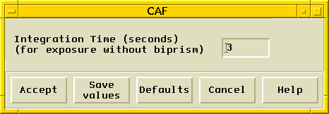
Now, open the CAF form from the menubar (Figure 12). Enter the exposure
time used for the test image. After clicking on "accept", the
focussing sequence starts. This involves several steps and requires
some input from the user:
- The Hartmann prism/hole device is driven automatically into the (collimated) beam.
- An image is automatically taken and displayed for processing.
- You should click on "cursor" then "region" in SAOIMAGE, then
select star images by clicking with the cursor on the LEFT image of
each pair; when the series is completed, select "write" on SAOIMAGE,
hit "return" and quit by typing "q" on the keyboard
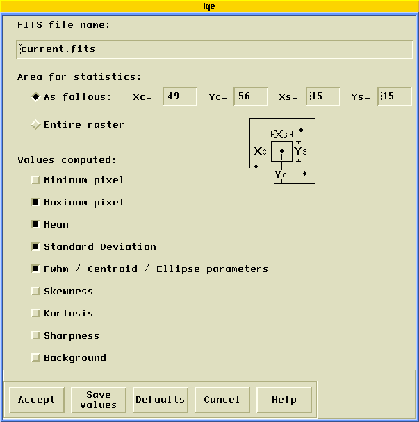
- CAF will find the barycenter of the images with the IQE routine
(figure 5.5) and compute the corresponding telescope focus motion
required, based on an internal calibration. The value is then
displayed in a separate window.
- The Hartmann mask is taken out of the beam and the grism wheel
returns to the previously selected position. Now, you simply add
(taking the sign into account) the suggested value to the current
telescope focus by using the telescope handpaddle. Normally you need
to run CAF only once. If you want to check the precision you can run
CAF a second time and you should not find a focus difference larger
than +/- 5 units (the accuracy depends, of course, of the actual
seeing).
Note: if, for any reason, you intend to run CAF
several times, you will save time by setting the grism wheel to
position 1 before starting the sequence.
FIGURE 13. The IQE form
OFFSET and OSIS-Ofst windows: accurate offsetting
There are 2 procedures for offsetting with the OSIS-OFFSET
form. Telescope Offset is used when guiding with the Cassegrain
bonnette and for motions up to a few arcmin; OSIS-Offset is used with
the OSIS guide probe for motions less than 30 arcsec.
FIGURE 14. The OSIS-OFFSET form

The OFFSET procedures are as following:
- Make sure you are guiding (with Cass bonnette or OSIS).
- Take an image of the field to be offset and measure the position
of your object in CCD coordinates.
- Select OSIS-OFFSET.
- Enter the initial coordinates Xi, Yi of your object on the CCD
and the final coordinates Xf, Yf where it must be on the CCD after
the offset. Note: the offsets are in unbinned pixels. For
reference to binned images, you must scale the offset. In this case,
it may be easier to work with a relative offset, and set the start
coordinates to 0,0.
- Select the mode you want to use for the offset (OSIS-Offset or
Telescope Offset).
- Select "accept". Depending on the mode selected,
- OSIS Offset: the computer will move the OSIS guide probe by the
adequate amount and then move the telescope in order not to loose the
guide star. The accuracy of the offset is about 1/2 pixel, i.e. better
than 0.05" and is limited by the accuracy of the OSIS probe XY motion.
- Telescope Offset: the computer will move the telescope the
appropriate amount and then move the bonnette probe in order not to
loose the guide star. The accuracy of the offset is about 1 pixel,
i.e. better than 0.1" and is limited by the accuracy of the bonnette's
mirror XY motion .
RASTER and EXPOSE windows: gathering photons
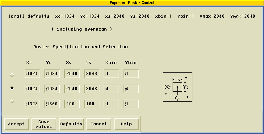
The RASTER window (Figure 15)
enables the oberver to define sub-frame and binning parameters. Three
configurations can be defined in advance and selected at will. To
select one of these three configurations, first click in the box in
front of the selection, then click on "accept". The selected raster is
displayed in the feedback window. Do not change the
raster while the EXPOSE window (see below) is open, as any changes in
the raster will not take place until the EXPOSE window is closed and
then opened again. Note: With EEV1, there may be some
confusion about the exact raster definition. EEV1 consists of 4500
physical rows on the chip, but only 3900 may be read out. The standard
raster has a central row of 2200, which leave 250 unread rows at the
start of the chip. Since the central pixels in the RASTER (and
FRASTER) forms refer to the physical chip pixels, this 250 offset must
be included when subrasters are selected.
FIGURE 15. The RASTER form
The EXPOSE window (Figure 16)
is used for defining and starting an exposure and is self
explanatory. Do not forget to select the correct exposure
type. Observing with 'calibration' automatically turns on
selected lamps and places the central mirror in the beam. Observing
with 'focus' uses the subraster selected in FRASTER, not RASTER.
Before starting an exposure, it makes sense to double check the
parameters of the exposure: configuration (mask, filter, grism),
raster (frame size, binning), exposure type, etc.
FIGURE 16. The EXPOSE form

LAMPS window: calibration unit control
The selection of calibration lamps is done before starting an exposure
from the LAMPS window (Figure
17). Simply click on the appropriate box(es) to select the
lamp(s) of interest. Note that each entry represents a pair of
identical lamps: two symetrically located lamps are used to provide
uniform illumination. You can select different lamps at once if
needed, and select different exposure times for the lamps
independently. The lamps will be fired when you start an exposure
with EXPOSE (do not forget to select 'calibration' as the exposure
type). If you have selected 'Timing On' in the LAMPS form, then the
lamps will be turned off as their exposure times expire. 'Timing Off'
uses the total calibration exposure time for all lamps. See in the
next chapter for the recommended calibration exposures. After
activating the needed calibrations with the corresponding "enable"
buttons, the whole sequence is started by clicking on "accept".
FIGURE 17. The LAMPS control form
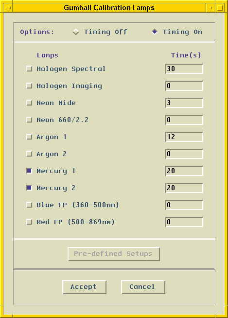
IMAGE and GRAPH windows: looking at the data
Normally, after each readout of the CCD, the new image is displayed as
a grey scale in an SAOIMAGE window
(Figure 18). If you want to look
at a previous image, click on the icon IMAGE and enter the file name:
for example, 299742o.fits. Then, in the SAOIMAGE window, you can
interactively adjust the grey scale levels, the scale ("histeq" is
fine for low contrast spectra, "sqrt" is better for direct images),
zoom (option "pan") and so on. Do not forget to return to
"current.fits" in IMAGE when you want an automatic display again.
FIGURE 18. The SAOIMAGE window. The object near
center is Markarian 876. Note the large occultation by the guide probe
in this test conducted with a guide star well within the science
field.

With a bonnette rotation of 0, North is down, and East is to the left.
The image rotates clockwise with increasing bonnette angle until North
is to the right for a rotation of +90.
The GRAPH window (Figure 19) enables displays of
cuts along rows or columns for up to 3 files simultaneously. You can
enter the file numbers themselves or the aliases current.fits and
previous.fits. The full capabilities of GRAPH are described in more
detail in the "Pegasus User's Manual"
It is possible to make hard-copies of the images displayed with IMAGE
and GRAPH.
FIGURE 19. The GRAPH form

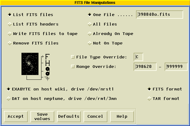
FILES window: handling data files
The FILES window (Figure 20) is used to remove files from the disk when space is needed and to transfer files to DAT or Exabyte tapes. Normally, the observer should transfer all of the files they will need for their subsequent data processing to tapes at the end of each night or at the end of the run. Under exceptional circumstances, it is still possible to retrieve files from the archive tapes in Waimea if, for some reason, useful files are missing. In such cases, ask your support astronomer for help. However, we insist this is not the normal way to save your data.
The FILES window also allows the user to read file headers, which contain a great deal of informations about the data such as object identification, coordinates, time, air mass, OSIS status, CCD status, and so on.
FIGURE 20. The FILES window
[Contents]
[Prev]
[Next]
Send comments to: eugene@cfht.hawaii.edu
Copyright © 1997, CFHT Corporation. All rights reserved.


